
ACM4-Series Instructions

- 4 - ACM4 series
connect the positive (+) input of the device being powered to the terminal marked [NC]. For Fail-Secure operation
connect the positive (+) input of the device being powered to the terminal marked [NO].
(b) Form “C” outputs (ACM4/ACM4E):
When form “C” outputs are desired the corresponding output fuse (1-4) must be removed. Connect negative (-) of
the po
wer supply directly to the locking device. Connect the positive (+) of the power supply to the terminal marked
[C]. For Fail-Safe operation connect the positive (+) of the device being powered to the terminal marked NC]. For
Fail-Secure operation connect the positive (+) of the device being powered to the terminal marked [NO].
(c) Auxiliary Power outputs (unswitched):
Connect positive (+) input of the device being powered to the terminal marked [C] and the negative (-) of the device
being po
wered to the terminal marked [COM]. Output can be used to provide power for card readers, keypads etc.
Note: When wiring for power-limited outputs utilize a knockout separate from the one used for
non po
wer-limited wiring.
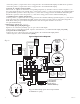
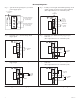
4. Input trigger options (Fig. 1, pg. 4):
(a) Normall
y Open [NO] input trigger:
Inputs 1-4 are activated by normally open or open collector sink inputs.
Connect de
vices (card readers, keypads, request to exit buttons etc.) to terminals marked [IN] and [GND].
(b) Open Collector Sink inputs:
Connect the access control panel open collector output to the terminal marked [IN] and the
common (ne
gative) to the terminal marked [GND].
NC C NO COM
OUTPUT1
NC C NO COM
OUTPUT2
NO C NC
FACP
--- + --- +
Power Control
+ INP --- T + RET ---
INTERFACE
L
ED1
S
W1 SW2 SW3
S
W4
L
ED2 LED3 LED4
TRIGGER
INPUT
T
RG
NC C NO COM
OUTPUT3
NC C NO COM
OUTPUT4
J2 J1
J
3
ACM4
A
CCESS POWER
CONTROLLER
LED1
SW1 SW2
LED2
IN GND
2
IN GND
1
IN GND
3
IN GND
4
NC
NO
C
KEYPAD
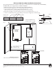
NORMALLY OPEN
N.O. DOOR
RELEASING
DEVICE
ACCESS CONTROL
PANEL
OUTPUT
RELAY
MAG.
LOCK
MAG.
LOCK
ELECTRIC
STRIKE
ELECTROMAGNETIC
DOOR HOLDERS
LISTED
AC or DC
ACCESS CONTROL
POWER SUPPLY
(optional)
FACP
(Fire Alarm
Control Panel)
LISTED
AC or DC
ACCESS CONTROL
POWER SUPPLY
(req’d)
UL Listed Power-Limited Power Supply
For this application
corresponding fuse
must be removed.
(ACM4 and ACM4E only)
FACP Interface Enabled
FACP Interface Disabled
SW1-SW4
ACM4CB
FACP Dry
Form "C"
Output
NO C NC
FACP
3A
1
0A
3A3A3A
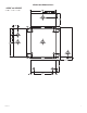
Keep power limited wiring separate from non-power limited.
Use minimum .25" spacing.
Fig. 1
Fig. 1a
Typical Application Diagram: