
ACM4-Series Instructions

ACM4 series - 5 -
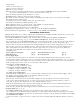
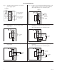
5. Fire Alarm Interface options (Figs. 3 through 7, pg. 6):
A nor
mally closed [NC], normally open [NO] input or polarity reversal input from FACP signaling circuit will
trigger selected outputs. To enable FACP Disconnect for an output open the corresponding switch [SW1-SW4].
To disable FACP disconnect for an output close the corresponding switch [SW1-SW4].
(a) Normally Open [NO] input:
For non-latching hook-up (Fig. 4, pg. 6). For latching hook-up (Fig. 5, pg. 6).
(b) Normally Closed [NC] input:
For non-latching hook-up (Fig. 6, pg. 6). For latching hook-up (Fig. 7, pg. 6).
(c) FACP Signaling Circuit input trigger:
Connect the positive (+) and negative (-) from the FACP signaling circuit output to the terminals marked [+ INP -].
Connect the F
ACP EOL to the terminals marked [+ RET -] (polarity is referenced in an alarm condition).
Jumper J3 must be cut (Fig. 3, pg. 6).
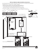
6. FACP Dry form “C” output (Fig. 1a, pg. 4):
Connect desired device to be triggered by the unit’s dry contact output to the terminals marked [NO] and [C]
F
ACP for normally open output or the terminals marked [NC] and [C] FACP for normally closed output.
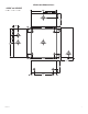
7. Installation of tamper switch (Not Included):
Mount UL Listed tamper switch (Sentrol model 3012 or equivalent) at the top of the enclosure. Slide the tamper
switch brack
et onto the edge of the enclosure approximately 2” from the right side.
Connect tamper switch wiring to the Listed Access Control Panel input or the appropriate UL Listed reporting device,
to activate alarm signal when the door of the enclosure is open.
Maintenance:
Unit should be tested at least once a year for the proper operation. Voltage on each output has to be tested for both
trigger and non-trigger states and operation of FACP interface has to be simulated.
LED Diagnostics:
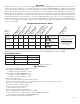
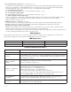
Terminal Identification Tables:
LED ON OFF
LED 1 - LED 4 (Red) Output relay(s) energized. Output relay(s) de-energized.
TRG (Green) FACP input triggered (alarm condition). FACP normal (non-alarm condition).
Terminal Legend Function/Description
-- Power + 12VDC to 24VDC input from UL Listed Access Control Power Supply.
-- Control +
These terminals can be connected to a separate, UL Listed Access Control Power Supply to
provideisolated operating power for the ACM4/ACM4E/ACM4CB/ACM4CBE (jumpers
J1and J2 Must be removed).
TRIGGER
INPUT 1 - INPUT 4
IN, GND
From normally open and/or open collector sink trigger inputs
(request to exit buttons, exit pir’s, etc.).
OUTPUT 1 - OUTPUT 4
NC, C, NO, COM
12 to 24 volts AC/DC trigger controlled outputs:
Fail-Safe [NC positive (+) & COM Negative (-)],
Fail-Secure [NO positive (+) & COM Negative (-)],
Auxiliary output [C positive (+) & COM Negative (-)]
(When using AC power supplies polarity need not be observed),
NC, C, NO become form “C” 5 amp 24VAC/VDC rated dry outputs when fuses are
removed (ACM4/ACM4E). Contacts shown in a non-triggered state.
FACP INTERFACE
T, + INPUT --
Fire Alarm Interface trigger input from FACP. Trigger inputs can be normally open,
normally closed from an FACP output circuit (Fig. 3 through 7, pg. 6).
FACP INTERFACE
NC, C, NO
Form “C” relay contact rated @ 1 amp 28VDC for alarm reporting.
(This output has not been evaluated by UL).