
ACM4-Series Instructions
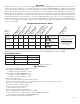
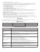

- 6 - ACM4 series
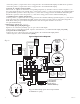
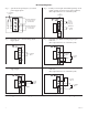
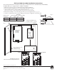
Hook-up Diagrams:
NO C NC
FACP
+ INP --- T + RET ---
INTERFACE
TRG
J3
JUMPER
N.C. DRY
TRIGGER
INPUT
Fig. 4 Normally Open - Non-Latching FACP
trigger input:
NO C NC
FACP
+ INP --- T + RET ---
INTERFACE
TRG
J3
N.C. TRIGGER
INPUT
N.C. RESET
SWITCH
JUMPER
Fig. 5 Normally Open FACP Latching trigger input
with reset:
(This output has not been evaluated by UL)
Fig. 6 Normally Closed - Non-Latching FACP
trigger input:
Fig. 7 Normally Closed - Latching FACP trigger input
with reset:
(This output has not been ev
aluated by UL)
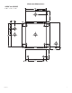
Fig
. 3 Polarity reversal input from FACP signaling circuit
output (polarity is referenced in alarm condition):
(This output has not been evaluated by UL)
Fig. 2 Optional hook-up using two (2) isolated
po
wer supply inputs:
CUT JUMPERS
J1 AND J2
ISOLATED POWER INPUT
1
2 OR 24VAC OR VDC
(LOCK POWER)
ISOLATED POWER INPUT
1
2 OR 24VAC OR VDC
(ACM4 POWER)
--- + --- +
Power Control
J2 J1
CUT
JUMPER J3
FROM FACP
CONTROL
CIRCUIT
+
--
FACP
CONTROL
CIRCUIT EOL
(if employed)
NO C NC
FACP
+ INP --- T + RET ---
INTERFACE
TRG
J3
NO C NC
FACP
+ INP --- T + RET ---
INTERFACE
TRG
J3
N.O. TRIGGER
INPUT
NO C NC
FACP
+ INP --- T + RET ---
INTERFACE
TRG
J3
N.C. RESET
SWITCH
N.O.
TRIGGER
INPUT
JUMPER
Note: Keep power limited wiring separate from non-power limited. Use minimum .25" spacing.