M220 Series Multi-Output Access Control Power Supply/Chargers Models Include: AL300M220 AL1012M220 AL400M220 AL1024M220 - 2.5A @ 12VDC or 24VDC - 4A @ 12VDC or 3A @ 24VDC - 10A @ 12VDC - 10A @ 24VDC AL600M220 - 6A @ 12VDC or 24VDC For a red enclosure add an “R” suffix to the part #, e.g. AL300MR220 Installation Guide Rev. 111103 More than just power.TM Installing Company: ________________ Service Rep.
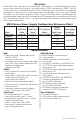
Overview: Altronix M220 Series multi-output access control power supply/chargers are specifically designed for use with access control systems and accessories. These units convert a 220VAC (working range 198VAC - 256VAC), 50/60Hz input into five (5) individually protected 12VDC or 24VDC outputs (see specifications). Each output will route power to a variety of access control hardware devices including Mag Locks, Electric Strikes, Magnetic Door Holders, etc.
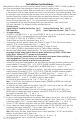
Installation Instructions: Wiring methods shall be in accordance with the National Electrical Code/NFPA 70/NFPA 72/ANSI, and with all local codes and authorities having jurisdiction. Product is intended for indoor use only. 1. Mount unit in the desired location. Mark and predrill holes in the wall to line up with the top two keyholes in the enclosure. Install two upper fasteners and screws in the wall with the screw heads protruding.
Maintenance: Unit should be tested at least once a year for the proper operation as follows: Output Voltage Test: Under normal load conditions the DC output voltage should be checked for proper voltage level (Output Voltage and Stand-by Specification Charts, pg. 4). Battery Test: Under normal load conditions check that the battery is fully charged, check specified voltage at the battery terminals and at the board terminals marked [– BAT +] to ensure that there is no break in the battery connection wires.
Output Voltage and Stand-by Specification Charts: AL300M220 Switch Position Output 12VDC/40AH Battery 24VDC/12AH Battery 24VDC/40AH Battery ON 4 hr. of Stand-by & 5 Minutes of Alarm Stand-by = 2.5A Alarm = 2.5A OFF – OFF Stand-by = 2.5A Alarm = 2.5A 24 hr. of Stand-by & 5 Minutes of Alarm Stand-by = 1.0A Alarm = 2.5A Stand-by = 200mA Alarm = 2.5A Stand-by = 1.0A Alarm = 2.5A 60 hr. of Stand-by & 5 Minutes of Alarm Stand-by = 300mA Alarm = 2.5A 24 hr.
Fig. 1 - AL300M220 and AL400M220 CAUTION: De-energize unit prior to servicing. For continued protection against risk of electric shock and fire hazard replace fuses with the same type and rating (see marking on the board). Do not expose to rain or moisture.
Fig. 2 - AL600M220 CAUTION: De-energize unit prior to servicing. For continued protection against risk of electric shock and fire hazard replace fuses with the same type and rating (see marking on the board). Do not expose to rain or moisture.
Fig. 3 - AL1012M220 CAUTION: De-energize unit prior to servicing. For continued protection against risk of electric shock and fire hazard replace fuses with the same type and rating. Do not expose to rain or moisture. - DC + Ground Lug Wire Strap AC DC Battery connections AC Delay + BAT - (from Enclosure to Door) 220VAC power mains L G N BAT FAIL NC C NO NC C NO AC FAIL Fig.
Fig. 4 - AL1024M220 CAUTION: De-energize unit prior to servicing. For continued protection against risk of electric shock and fire hazard replace fuses with the same type and rating (see marking on the board). Do not expose to rain or moisture. + DC - Ground Lug Wire Strap AC AC FAIL C NO NC BAT FAIL C NO NC G N AC DELAY - DC INPUT + Battery & AC Supervision Circuit - INPUT + AC FAIL MOM5_S DC Outputs to devices TRIGGER C NO NC NO C NEG1 NEG2 NEG3 NEG4 NEG5 NC BAT FAIL Fig.
Power Supply Board Terminal Legend L, G, N + DC – Terminal Identification Tables: Function/Description Connect 220VAC, 50/60Hz to these terminals: L to hot, N to neutral. AL300M220 - 12VDC/24VDC @ 2.5A to MOM5 board. AL400M220 - 12VDC @ 4A or 24VDC @ 3A to MOM5 board. AL600M220 - 12VDC/24VDC @ 6A to MOM5 board. AL1012M220 - 12VDC @ 10A to MOM5 board. AL1024M220 - 24VDC @ 10A to MOM5 board. AC FAIL NC, C, NO Indicates loss of AC power, e.g. connect to audible device or alarm panel.
Typical Application Diagrams: Fig. 5 (-) DC VOLTAGE INPUT FROM FACP SIGNALING OUTPUT OR ACCESS CONTROL DEVICE NEG (-) INPUT POS (+) (+) MOM5 module shown with wet and/or dry normally open trigger inputs (Non-Latching): EOL 2.2K (+) (-) DC VOLTAGE INPUT FROM FACP SIGNALING OUTPUT OR ACCESS CONTROL DEVICE EOL 2.2K TRIGGER TRIGGER NEG (-) INPUT POS (+) MOM5 module shown with wet and/or dry normally closed trigger inputs (Non-Latching): N.C. INPUT FROM FACP OR ACCESS CONTROL DEVICE N.O.
Typical Application Diagrams (cont’d): Fig. 8 (+) (-) MOM5 module shown with with wet and/or dry normally closed fire alarm trigger inputs (Latching with Manual Reset): NEG (-) INPUT POS (+) NEG (-) INPUT POS (+) MOM5 module shown with with wet and/or dry normally open fire alarm trigger inputs (Latching with Manual Reset): DC VOLTAGE INPUT FROM FACP SIGNALING OUTPUT (-) DC VOLTAGE INPUT FROM FACP SIGNALING OUTPUT TRIGGER TRIGGER EOL 2.2K (+) EOL 2.2K N.C. INPUT FROM FACP SIGNALING OUTPUT N.O.
AL1024M220 Battery Size Calculation Worksheet. A. AL1024M220 internal current consumption (stand-by) 0.13A B. Load current consumption (stand-by) A C. Stand-by time required (hours) H D. Battery capacity required for stand-by (A+B)*C AH E. AL1024M220 internal power consumption (Alarm) 0.13A F. Load current consumption (Alarm) A G. Alarm duration (Hours, example: 15 Min = 0.25 Hour) (Alarm) H H. Battery capacity required for Alarm (E+F)*G AH0 I.
Notes: - 14 - M220 Series Installation Guide
Enclosure Dimensions (H x W x D) for: AL300M220 • AL400M220 • AL600M220 13.5” x 13” x 3.25” (342.9mm x 330.2mm x 82.6mm) 1.40” (35.6mm) 4.85” (123.2mm) 4.85” (123.2mm) 1.40” (35.6mm) 1.20” (30.5mm) 0.75” (19.1mm) 3.25” (82.6mm) 1.20” (30.5mm) 0.75” (19.1mm) 12.5” (317.5mm) 11.0” (279.4mm) 1.20” (30.5mm) 0.9375” (23.8mm) 1.40” (35.6mm) 1.40” (35.6mm) 5.10” (129.5mm) 5.10” (129.5mm) 13.0” (330.2mm) 6.5625” (166.7mm) 5.10” (129.5mm) 0.9375” (23.8mm) 3.25” (82.6mm) 3.25” (82.6mm) 3.25” (82.
Enclosure Dimensions (H x W x D) for: AL1012M220 • AL1024M220 15.5” x 12” x 4.5” (393.7mm x 304.8mm x 114.3mm) 1.5” (38.1mm) 4.615” (117.2mm) 4.615” (117.2mm) 1.5” (38.1mm) 1.75” (44.5mm) 1.25” (31.8mm) 4.5” (114.3mm) 1.1” (27.9mm) 12.23” (310.6mm) 4.5” (114.3mm) 1.1” (27.9mm) 1.375” (34.9mm) 1.5” (38.1mm) 1.25” (31.8mm) 1.5” (38.1mm) 0.91” (23.1mm) 0.91” (23.1mm) 1.125” (28.6mm) 15.5” (393.7mm) 2.0” (50.8mm) 2.0” (50.8mm) 5.0” (127.0mm) 0.79” (20.1mm) 5.0” (127.0mm) 1.25” (31.8mm) 1.