AL1024NK1 Dual Output Power Supply/Charger Kit Fully assembled kit includes: - (1) AL1024ULXB2 - Power Supply/Charger - (1) VR6 - Voltage Regulator Installation Guide Rev. 1024NK1_022322 More than just power.TM Installing Company: ________________ Service Rep.
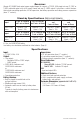
Overview: Altronix AL1024NK1 dual output power supply/charger kit converts a 115VAC, 60Hz input into one (1) 5VDC or 12VDC selectable output at up to 6A supply current and one (1) 24VDC output. It also offers a suite of features that includes overvoltage protection, AC fail supervision, low battery supervision and battery presence supervision (form “C” contacts). Stand-by Specifications (total current shown): Output 15 min. of Stand-by 4 hr. of Stand-by and 5 min. of Alarm and 5 min.
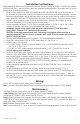
Installation Instructions: Wiring methods shall be in accordance with the National Electrical Code/NFPA 70/NFPA 72/ANSI, The Canadian Electrical Code, Part 1 and with all local codes and authorities having jurisdiction. The product must be located indoors within the protected premises. 1. Mount unit in desired location. Mark and predrill holes in the wall to line up with the top two keyholes in the enclosure. Install two upper fasteners and screws in the wall with the screw heads protruding.
LED Diagnostics: AL1024ULXB2 - Power Supply/Charger Red (DC) ON ON OFF OFF Green (AC/AC1) ON OFF ON OFF Power Supply Status Normal operating condition. Loss of AC. Stand-by battery supplying power. No DC output. Loss of AC. Discharged or no stand-by battery. No DC output. Terminal Identification: AL1024ULXB2 - Power Supply Board Terminal Legend L, N + DC – AC Fail NC, C, NO Function/Description Connect 115VAC to these terminals: L to hot, N to neutral (Fig. 1a, pg. 4). Factory connected to VR6 (Fig.
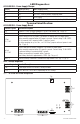
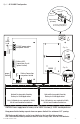
Fig. 2 - AL1024NK1 Configuration Enclosure Edge of Enclosure Tamper Switch (included) To Access Control Panel or UL Listed Reporting Device power mains VAC115VAC power mains non power-limited power-limited L G N 115VAC power mains non power-limited ON-5V OFF-12V Green Lead Fig.
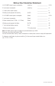
Battery Size Calculation Worksheet: A. AL1024NK1 internal current consumption (stand-by) ________________ 0.05 A B. Load current consumption (stand-by) ________________ A C. Stand-by time required (hours) ________________ H D. Battery capacity required for stand-by (A+B)*C ________________ AH E. AL1024NK1 internal power consumption (Alarm) ________________ 0.05 A F. Load current consumption (Alarm) ________________ A G. Alarm duration (Hours; 15 Min. = 0.
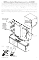
NEC Power-Limited Wiring Requirements for AL1024NK1: Power-limited and non power-limited circuit wiring must remain separated in the cabinet. All power-limited circuit wiring must remain at least 0.25” away from any non power-limited circuit wiring. Furthermore, all power-limited circuit wiring and non power-limited circuit wiring must enter and exit the cabinet through different conduits. One such example of this is shown below. Your specific application may require different conduit knockouts to be used.
Enclosure Dimensions (BC300): 13.5” x 13” x 3.25” (342.9mm x 330.2mm x 82.6mm) 1.40” (35.6mm) 4.85” (123.2mm) 4.85” (123.2mm) 1.40” (35.6mm) 1.20” (30.5mm) 0.75” (19.1mm) 3.25” (82.6mm) 1.20” (30.5mm) 0.75” (19.1mm) 12.5” (317.5mm) 11.0” (279.4mm) 1.20” (30.5mm) 0.9375” (23.8mm) 1.40” (35.6mm) 1.40” (35.6mm) 5.10” (129.5mm) 5.10” (129.5mm) 13.0” (330.2mm) 6.5625” (166.7mm) 5.10” (129.5mm) 0.9375” (23.8mm) 3.25” (82.6mm) 3.25” (82.6mm) 3.25” (82.6mm) 1.0” (25.4mm) 1.0” (25.4mm) 10.