
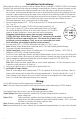
Installation Instructions


AL1024NK8(D) Installation Guide - 5 -
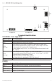
Fig. 2 - AL1024ULXB2 Board Configuration
2a 2b
2d
2c
2e
2f
L
G
N
BAT FAIL
AC FAIL
NC
C
NO
NC
C
NO
AC
DC
- BAT +
+ DC -
AC DELAY
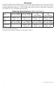
Terminal Identification:
AL1024ULXB2 - Power Supply Board
Terminal Legend Function/Description
L, N Connect 115VAC to these terminals: L to hot, N to neutral (Fig. 2a, pg. 5).
+ DC – Factory connected to PDS8(CB) (Fig. 2d, pg. 5).
AC Fail
NC, C, NO
Used to notify loss of AC power, e.g.connect to audible device or alarm panel.
Relay normally energized when AC power is present. Contact rating 1A @ 28VDC.
AC or brownout fail is reported within 1 minute of event.
To delay reporting for up to 6 hrs., cut “AC Delay” jumper and reset power to unit
(Fig. 2f, pg. 5).
Bat Fail
NC, C, NO
Used to indicate low battery condition, e.g. connect to alarm panel.
Relay normally energized when DC power is present. Contact rating 1A @ 28VDC.
A removed battery is reported within 1 minute.
Battery reconnection is reported within 1 minute.
Low battery threshold: approximately 21VDC (Fig. 2b, pg. 5).
– BAT + Stand-by battery connections. Maximum charge current 3.6A (Fig. 2c, pg. 5).
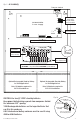
PDS8(CB):
Terminal Legend Function/Description
+ INP1 – Factory connected to AL1024ULXB2. Do not use these terminals.
+ INP2 – Factory connected to AL1024ULXB2. Do not use these terminals.
P [OUT1-OUT8] Positive DC power outputs.
N [OUT1-OUT8] Negative DC power outputs.