
Installation Instructions


AL1024NK8(D) Installation Guide - 7 -
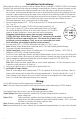
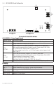
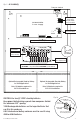
Fig. 3 - AL1024NK8(D)
DC Output to devices
(AL1024NK8 - non power-limited, AL1024NK8D - power-limited)
Tamper Switch
PTC
Protected
Outputs on
AL1024NK8D
PDS8(CB)
+ INP1
--
PWR1 +
OFF
IN1
IN2
Out1
<
1 off 2
>
PWR1 +
PWR2 +
PWR2 +
COM (--- )
COM (--- )
+ INP2
--
IN2 Fuse
IN1 Fuse
Common Power Outputs (NEG)
N
P
OUT1 OUT2 OUT3 OUT4 OUT5 OUT6 OUT7 OUT8
1 2 3 4 5 6 7 8
10
10
3
3
333333
Out2
<
1 off 2
>
Out3
<
1 off 2
>
Out4
<
1 off 2
>
Out5
<
1 off 2
>
Out6
<
1 off 2
>
Out7
<
1 off 2
>
Out8
<
1 off 2
>
AL1024ULXB2
Power Supply
L
G
N
BAT FAIL
AC FAIL
NC
C
NO
NC
C
NO
AC
DC
- BAT +
+ DC -
AC DELAY
Power Output
Factory wired to
PDS8(CB) and VR6
(non power-limited)
Battery Output
(non power-limited)
Supervisory connections (power-limited)
Spade Lugs to connect
to the compatible board
24VDC from
AL1024ULXB2
12VDC from VR6
(factory connected)
Optional Rechargeable Stand-by Battery
for UL294 Applications
Note: 12V batteries required for
ULC-S319 installations.
Optional Rechargeable Stand-by Battery
for UL294 Applications
Note: 12V batteries required for
ULC-S319 installations.
CAUTION: Use two (2) 12VDC stand-by batteries.
Keep power-limited wiring separate from non power-limited.
Use minimum 0.25” spacing.
12AH Rechargeable batteries are the largest batteries that
can fit in this enclosure.
A UL listed external battery enclosure must be used if using
40AH or 65AH batteries.
Tamper Switch
(included)
To Access Control Panel or
UL Listed Reporting Device
Edge of
Enclosure
Enclosure
Fig. 3a