AL1024NKA8QM Series Networkable Dual Output Access Power Controllers Models Include: AL1024NKA8QM - 12VDC and/or 24VDC (240W total power) selectable by output. Eight (8) programmable fuse protected outputs Eight (8) programmable trigger inputs Built-in Charger for sealed lead acid or gel type batteries AL1024NKA8DQM - 12VDC and/or 24VDC (240W total power) selectable by output.
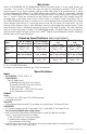
Overview: Altronix AL1024NKA8QM and AL1024NKA8DQM distribute and switch power to access control systems and accessories. They convert a 1150VAC 60Hz input into eight (8) independently controlled 12VDC or 24VDC protected outputs. Access Power Controller’s dual input design allows power to be steered from two (2) factory installed independent low voltage 12 or 24VDC Altronix power supplies to eight (8) independently controlled fuse (AL1024NKA8QM) or PTC (AL1024NKA8DQM) protected outputs.
• Any of the eight (8) fuse/PTC protected power outputs are selectable to follow power Input 1 or Input 2. Output voltage of each output is the same as the input voltage of the input selected. • Surge suppression. Fuse/PTC Ratings: AL1024ULXB2: - Input fuse is rated 5A/250V. - Battery fuse rated 15A/32V. LINQ8ACM: - Main input fuse is rated 15A/32V. - Output fuses are rated 3A/32V. LINQ8ACMCB: - Main input PTC is rated 9A. - Output PTCs are rated 2A.
• Eight (8) programmable trigger inputs: - Normally open (NO). - Normally colsed (NC). - Open collector sink inputs. - Wet Input (5VDC - 24VDC) with 10k resistor. - Any combination of the above. • Programmable port IDs. • Monitor power supply(ies) input for voltage and currect limits (high/low). • Input and output current calibration. • Programmable timer events. • Programmable user levels. • Enable or disable alerts by type.
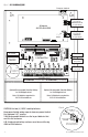
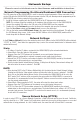
8. Input Trigger Options (program trigger input options via LINQ software): Note: If Fire Alarm disconnect is not used, connect a 10 kOhm resistor to terminals marked [GND and EOL]. Input: Connect dry access control (NC/NO) input to terminals marked [+ INP1 –] to [+ INP8 –]. Open Collector Sink Input: Connect the open collector sink input to the terminal marked [+ INP1 –] to [+ INP8 –].
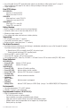
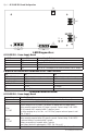
Fig. 2 - AL1024ULXB2 Board Configuration AC FAIL C NO NC C NO BAT FAIL 2a + DC - BAT + DC 2d 2c 2f NC N G L AC 2e AC DELAY 2b LED Diagnostics: AL1024ULXB2 - Power Supply Board Red (DC) ON ON OFF OFF Green (AC) ON OFF ON OFF Power Supply Status Normal operating condition. Loss of AC. Stand-by battery is supplying power. No DC output. Loss of AC. Discharged or no stand-by battery. No DC output.
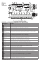
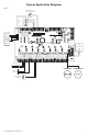
S R Q P X NO NC C NO Y + INP6 - + INP7 - + INP8 - V BAT 1 FUSE C AC Z PWR1 OFF U PWR2 + PWR2 - NC t8 Ou t7 Ou t6 Ou t5 Ou t4 Ou t3 Ou t2 Ou t1 Ou at Be CP FA T BA + PWR1 - B + INP5 - C L FACP K G F- PWR2<-->PWR1 OUT8 PWR2<-->PWR1 OUT7 PWR2<-->PWR1 OUT6 PWR2<-->PWR1 OUT5 PWR2<-->PWR1 OUT4 PWR2<-->PWR1 OUT3 PWR2<-->PWR1 OUT2 PWR2<-->PWR1 OUT1 N M EN<-->DIS W D + PS2 - T + BAT - + INP4 - + PS1 - + INP3 - R- GND GND C R+ EOL RST NC + INP2 - AC NC COM NO C
Fig.
Typical Application Diagram: Fig. 5 Normally Open (N.O.
Network Setup: –––––––––––––––––––––––––––––––––––––––––––––––––––––––––––––––––––––––––––––––––––––––––– Please be sure to visit altronix.com for latest firmware and installation instructions. –––––––––––––––––––––––––––––––––––––––––––––––––––––––––––––––––––––––––––––––––––––––––– Network Programming Via Altronix Dashboard USB Connection: The USB connection on the LINQ8ACM(CB) is used to setup the network parameters.
How to Upload Certificate and Key to Setup HTTPS: 1. Open Tab Labeled Security. 2. Select Tab Labeled Email/SSL. 3. Scroll to bottom under SSL Settings. 4. Click Select Certificate. 5. Browse and select valid Certificate to upload from server. 6. Click Select Key. 7. Browse and select valid Key to upload from server. 8. Click Submit Files. Once the Certificate and Key is uploaded successfully you can proceed with setting up HTTPS in Network Settings. a.
A. Hardware Setup: Click on the Settings tab to open the Hardware Setup screen. Input / Output Setup: 1. Click on the INPUT / OUTPUT tab at the top of the screen. 2. Output ID: Enter a descriptive name for the device connected to the associated output. 3. Output Control: using the pulldown menu select whether the output will be controlled via an access control input to the trigger terminals or software controlled. a. Input Control: outputs are controlled via the Trigger Input, b.
Output Current Calibration: During the initial setup all outputs need to be calibrated to insure accurate current readings. 1. Click on the Calibration tab at the top of the screen. 2. With all loads disconnected click on the tab labeled Calibrate All Zero Offset Currents to set all output currents to zero. 3. Connecting each output one at a time, measure the current draw and enter this value for this output under Actual. 4. Click on the button labeled Calibrate Gain to save the settings. 5.
d. HTTP Port: Enter the HTTP port number assigned to the Linq8ACM module by the network administrator to allow remote access and monitoring. The default inbound port setting is 80. HTTP is not encrypted and unsecure. Even though HTTP can be used for remote access it is recommended primarily for use with LAN connections. e. HTTPS Port: Enter the HTTPS port number assigned to the LINQ8ACM(CB) module by the network administrator to allow remote access and monitoring. The default inbound port setting is 443.
Certificate Upload: Uploading a private Certificate and Key. 1. Under Certificate upload click on Select Certificate File. 2. Locate the new certificate file. 3. Upload the certificate file. 4. Under Key upload click on Select Key File. 5. Locate the new certificate file. 6. Upload the Key file. 7. Click on the button labeled Submit file save settings User Settings: There are several programable user levels available. Administrator: Has access to all functions.
Hook-Up Diagrams: FACP R- GND GND C R+ EOL RST NC Jumper FCOM - COM - F- F+ Jumper F+ R- GND GND C R+ EOL RST NC FACP Fig. 6 - Daisy-chaining one or more LINQ8ACM(CB) units. EOL Jumper [EOL JMP] should be installed in the EOL position. Non-Latching. FACP R- GND GND C R+ EOL RST NC FCOM - COM - F- F+ N.O. Switch F+ R- GND GND C R+ EOL RST NC FACP Fig. 7 - Daisy-chaining one or more LINQ8ACM(CB) units. EOL Jumper [EOL JMP] should be installed in the EOL position. Latching Single Reset.
Hook-Up Diagrams: Polarity reversal input from FACP signaling circuit output (polarity is referenced in alarm conditiion). Non-Latching. Fig. 10 - Polarity reversal input from FACP signaling circuit output (polarity is referenced in alarm condition). Latching. FACP R- GND GND C R+ EOL RST NC Jumper EOL COM - COM - -- -- F- F- F+ + F+ EOL N.O. Switch + R- GND GND C R+ EOL RST NC FACP Fig. 9 - R- GND GND C R+ EOL RST NC Jumper N.O.
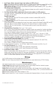
Battery Size Calculation Worksheet: A. AL1024NKA8(D)QM internal current consumption (stand-by) ________________ 0.05 A B. Load current consumption (stand-by) ________________ A C. Stand-by time required (hours) ________________ H D. Battery capacity required for stand-by (A+B)*C ________________ AH E. AL1024NKA8(D)QM internal power consumption (Alarm) ________________ 0.05 A F. Load current consumption (Alarm) ________________ A G. Alarm duration (Hours; 15 Min. = 0.
Notes: AL1024NKA8(D)QM Installation Guide - 19 -
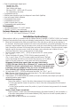
Enclosure Dimensions (BC400): 15.5” x 12” x 4.5” (393.7mm x 304.8mm x 114.3mm) 1.5” (38.1mm) 4.615” (117.2mm) 4.615” (117.2mm) 1.5” (38.1mm) 1.75” (44.5mm) 1.25” (31.8mm) 4.5” (114.3mm) 1.1” (27.9mm) 12.23” (310.6mm) 4.5” (114.3mm) 1.1” (27.9mm) 1.375” (34.9mm) 1.5” (38.1mm) 1.25” (31.8mm) 1.5” (38.1mm) 0.91” (23.1mm) 0.91” (23.1mm) 1.125” (28.6mm) 15.5” (393.7mm) 2.0” (50.8mm) 2.0” (50.8mm) 5.0” (127.0mm) 0.79” (20.1mm) 5.0” (127.0mm) 1.25” (31.8mm) 1.25” (31.8mm) 1.1” (27.9mm) 1.