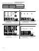
AL1024ULX Series Power Supply/Charger Installation Guide Models Include: • AL1024ULX - Single Output • AL1024ULXPD4 • AL1024ULXPD4CB • AL1024ULXPD8 • AL1024ULXPD8CB • AL1024ULXPD16 • AL1024ULXPD16CB - Four (4) Fused Outputs - Eight (8) Fused Outputs - Sixteen (16) Fused Outputs - Four (4) PTC Outputs - Eight (8) PTC Outputs - Sixteen (16) PTC Outputs For a red enclosure add an “R” suffix to the part #, e.g. AL1024ULXPD8R SECURITY SIGNALING LISTED LISTED Rev.
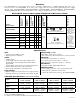
Overview: The AL1024ULX is a power supply that converts a 115VAC / 60Hz input to a 24VDC regulating output (see specifications below). The AL1024ULX is the base power supply unit for the UL Listed multi-output power supply/ charger series: AL1024ULXPD4, AL1024ULXPD4CB, AL1024ULXPD8, AL1024ULXPD8CB, AL1024ULXPD16, AL1024ULXPD16CB (Refer to AL1024ULX Series Power Supply Configuration Reference Chart below).
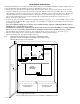
Installation Instructions: Wiring methods shall be in accordance with the National Electrical Code/NFPA 70/NFPA 72/ANSI, and with all local codes and authorities having jurisdiction. Product is intended for indoor use only. 1. Mount unit in the desired location. Mark and predrill holes in the wall to line up with the top two keyholes in the enclosure. Install two upper fasteners and screws in the wall with the screw heads protruding.
. Connect devices to be powered: a. For AL1024ULX Power Supply: connect devices to the terminals marked [+ DC --] (Fig. 1, pg. 3) b. For other Power Distribution Models: connect devices to be powered to terminal pairs 1 to 4 marked [1P & 1N] through [4P & 4N] (Fig. 2a & 2b, pg. 5) or 1 to 8 marked [1P & 1N] through [8P & 8N] (Fig. 3a & 3b, pg. 5), carefully observing correct polarity. 5. For Access Control applications batteries are optional.
Terminal Identification: PD4UL/PD4ULCB/PD8UL/PD8ULCB - Power Distribution Module Terminal Legend Function/Description PD4UL/PD4ULCB PD8UL/PD8ULCB 1P to 4P 1P to 8P Positive DC power outputs 1N to 4N 1N to 8N Negative DC power outputs Power Distribution Module(s): Fig. 2b BROOKLYN, NY 11220 F2 F3 1P, 2P, 3P, 4P = FUSED OUTPUTS 1N, 2N, 3N, 4N = COMMON OUTPUTS MADE IN USA F1 ALTRONIX CORP. Fig.
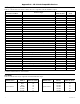
Appendix A - UL Listed Compatible Devices A.1 Four (4) Wire Smoke Detectors Table A-1 below lists four (4) wire smoke detectors compatible with AL1024ULX output.
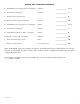
Battery size calculation worksheet: A. AL1024ULX series internal current consumption (stand-by) _______________________ 0.05 A B. Load current consumption (stand-by) _______________________ A C. Stand-by time required (hours) _______________________ H D. Battery capacity required for stand-by (A+B)*C _______________________ AH E. AL1024ULX series internal power consumption (Alarm) _______________________ 0.05 A F. Load current consumption (Alarm) _______________________ A G.
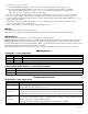
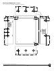
Enclosure Dimensions (BC400): 15.5” x 12” x 4.5” (393.7mm x 304.8mm x 114.3mm) 1.5” (38.1mm) 4.615” (117.22mm) 4.615” (117.22mm) 1.5” (38.1mm) 1.75” (44.45mm) 1.375” (34.925mm) 1.125” (28.575mm) 1.25” (31.75mm) 4.5” (114.3mm) 12.23” (310.64mm) 1.1” (27.94mm) 0.91” (23.114mm) 1.5” (38.1mm) 4.5” (114.3mm) 1.1” (27.94mm) 1.25” (31.75mm) 0.91” (23.114mm) 2.0” (50.8mm) 1.5” (38.1mm) 15.5” (393.7mm) 2.0” (50.8mm) 5.0” (127.0mm) 5.0” (127.0mm) 1.1” (27.94mm) 1.25” (31.75mm) 0.79” (20.