
Installation Manual
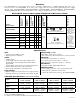

AL1024ULX series - 3 -
Installation Instructions:
WiringmethodsshallbeinaccordancewiththeNationalElectricalCode/NFPA70/NFPA72/ANSI,andwithalllocal
codes and authorities having jurisdiction. Product is intended for indoor use only.
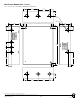
1. Mount unit in the desired location. Mark and predrill holes in the wall to line up with the top two keyholes in the
enclosure.Installtwoupperfastenersandscrewsinthewallwiththescrewheadsprotruding.Placetheenclosure’s
upper keyholes over the two upper screws; level and secure. Mark the position of the lower two holes. Remove the
enclosure.Drillthelowerholesandinstallthreefasteners.Placetheenclosure’supperkeyholesoverthetwo
upperscrews.Installthetwolowerscrewsandmakesuretotightenallscrews(Enclosure Dimensions, pg. 8).
Secure enclosure to earth ground.
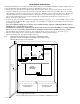
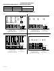
2. Connect AC power (115VAC / 60 Hz) to the terminals marked [L, N] (Fig. 1, pg. 3). Use 14 AWG or larger for all
power connections (Battery, DC output, AC input). Use 22 AWG to 18 AWG for power-limited circuits (AC Fail/
Low Battery reporting).
Keep power-limited wiring separate from non power-limited wiring (115VAC / 60Hz Input, Battery Wires).
Minimum 0.25” spacing must be provided.
CAUTION: Do not touch exposed metal parts. Shut branch circuit power before installing or servicing equipment.
There are no user serviceable parts inside. Refer installation and servicing to qualified service personnel.
For Fire Alarm applications the outputs are “Special Applications” only, see list (refer to Appendix A, pg. 6).
3. Measure output voltage before connecting device. This helps avoiding potential damage.
When servicing the unit, AC mains should be removed.
+ DC ---
– BAT +
BAT FAIL
NC C NO NC C NO
AC FAIL
DCAC
LGN
5A 250V
15
AC DELAY
15A 32V
Wire Strap
(from
Enclosure
to Door)
115VAC
power mains
non power-limited
Divider
CAUTION: De-energize unit prior to servicing. For continued protection
against risk of electric shock and fire hazard replace fuses with the same type
and rating. Do not expose to rain or moisture.
INPUT
1
2
Power
Distribution
Module(s)
Battery and AC
Supervision Circuit
(power limited).
non power-limited
Battery Connections
non power-limited
Class 1
Earth Ground
Keep power-limited wiring separate from non power-limited. Use minimum 0.25" spacing.
CAUTION: Optional rechargeable stand-by batteries must match
the power supply output voltage setting.
Optional Rechargeable
Stand-by Battery
Optional Rechargeable
Stand-by Battery
Fig. 1