
Installation Manual


- 4 - AL1024ULX series
4. Connect devices to be powered:
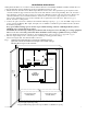
a. For AL1024ULX Power Supply: connect devices to the terminals marked [+ DC -- ] (Fig. 1, pg. 3)
b. For other Power Distribution Models: connect devices to be powered to terminal pairs 1 to 4 marked
[1P & 1N] through [4P & 4N] (Fig. 2a & 2b, pg. 5) or 1 to 8 marked [1P & 1N] through [8P & 8N]
(Fig. 3a & 3b, pg. 5), carefully observing correct polarity.
5. For Access Control applications batteries are optional. When batteries are not used, a loss of AC will result in
the loss of output voltage. When the use of stand-by batteries is desired, they must be lead acid or gel type.
6. Connectappropriatesignalingnotificationdevicestotheterminalsmarked[ACFAIL&BATFAIL](Fig. 1, pg. 3)
supervisory relay outputs.
Note: When used in fire alarm, burglar alarm or access control applications, “AC Fail” relay must be used to
provide a visual indication of AC power on.
7. Please ensure that the cover is secured with the provided Key Lock.
Wiring:
Use 14 AWG or larger for all power connections.
Note: Take care to keep power-limited circuits separate from non power-limited wiring (115VAC, Battery).
Maintenance:
Unit should be tested at least once a year for the proper operation as follows:
Output Voltage Test: Under normal load conditions the DC output voltage should be checked for proper voltage level.
Battery Test: Under normal load conditions check that the battery is fully charged, check specified voltage both at the
battery terminal and at the board terminals marked [– BAT + ] to ensure that there is no break in the battery connection wires.
Note: Maximum charging current under discharges is 3.6 amp.
Note: Expected battery life is 5 years; however, it is recommended changing batteries in 4 years or less if needed.
LED Diagnostics:
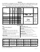
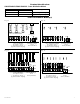
AL1024ULXB2-PowerSupplyBoard
Red (DC) Green (AC) Power Supply Status
ON ON Normal operating condition.
ON OFF Loss of AC. Stand-by battery supplying power.
OFF ON No DC output.
OFF OFF Loss of AC. Discharged or no stand-by battery. No DC output.
PD4UL/PD4ULCB/PD8UL/PD8ULCB-PowerDistributionModule
Green (AC) Power Distribution Module Status
ON Normal operating condition.
OFF No Power Output.
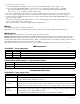
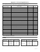
Terminal Identification:
AL1024ULXB2-PowerSupplyBoard
Terminal Legend Function/Description
L, N Connect 115VAC 60Hz to these terminals: L to hot, N to neutral. Do not use the [G] terminal.
+ DC ---
24VDC@8ampcontinuous,10ampinalarmnonpower-limitedoutput.
10 amp continuous when batteries are not used
AC Fail
NC, C, NO
IndicateslossofACpower,e.g.connecttoaudibledeviceoralarmpanel.Relaynormallyenergized
whenACpowerispresent.Contactrating1amp@28VDC.ACorbrownoutfailisreportedwithin
1 minute of event. To delay reporting for up to 6 hrs., cut “AC delay” jumper and reset power to unit.
Bat Fail
NC, C, NO
Indicateslowbatterycondition,e.g.connecttoalarmpanel.RelaynormallyenergizedwhenDC
powerispresent.Contactrating1amp@28VDC.Aremovedbatteryisreportedwithin5minutes.
Battery reconnection is reported within 1 minute.
Lowbatterythreshold:24VDCoutputthresholdset@approximately21VDC.
– BAT + Stand-by battery connections. Maximum charge current 3.6 amp.