AL1024ULX Series Power Supply/Charger Installation Guide Models Include: • AL1024ULX - Single Output • AL1024ULXPD4 - Four (4) Fused Outputs • AL1024ULXPD4CB - Four (4) PTC Outputs • AL1024ULXPD8 - Eight (8) Fused Outputs • AL1024ULXPD8CB - Eight (8) PTC Outputs • AL1024ULXPD16 - Sixteen (16) Fused Outputs • AL1024ULXPD16CB - Sixteen (16) PTC Outputs For a red enclosure, add an “R” suffix to the part # e.g. AL1024ULXPD8R Rev.
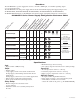
Overview: The AL1024ULX is a power supply that converts a 115VAC / 60Hz input, to a 24VDC regulating output (see specifications below). The AL1024ULX is the base power supply unit for the UL Listed multi-output power supply/charger series: AL1024ULXPD4, AL1024ULXPD4CB, AL1024ULXPD8, AL1024ULXPD8CB, AL1024ULXPD16, AL1024ULXPD16CB (Refer to AL1024ULX Series Power Supply Configuration Reference Chart below). AL1024ULX(R) - 1 - - - 10 AL1024ULXPD4 PD4UL 4 - x - 3.5 PD4ULCB 4 x - x 2.
Stand-by Specifications (total current shown): Output 24VDC / 12AH Battery Output 15 Min. of Stand-by & 5 Mins. of Alarm 4 hr. of Stand-by & 5 Mins. of Alarm 24 hr. of Stand-by & 5 Mins. of Alarm 60 hr. of Stand-by & 5 Mins. of Alarm Stand-by = 8 amp Alarm = 10 amp Stand-by = 1.5 amp Alarm = 10 amp Stand-by = 200mA Alarm = 10 amp Stand-by = 100mA Alarm = 10 amp 15 Min. of Stand-by & 15 Mins. of Alarm 4 hr. of Stand-by & 5 Mins. of Alarm 24 hr. of Stand-by & 15 Mins. of Alarm 60 hr.
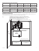
1. Mount unit in desired location. Mark and predrill holes in the wall to line up with the top two keyholes in the enclosure. Install two upper fasteners and screws in the wall with the screw heads protruding. Place the enclosure’s upper keyholes over the two upper screws, level and secure. Mark the position of the lower two holes. Remove the enclosure. Drill the lower holes and install the three fasteners. Place the enclosure’s upper keyholes over the two upper screws.
LED Diagnostics: PD4UL/PD4ULCB/PD8UL/PD8ULCB - Power Distribution Module Green Power Distribution Module Status ON Normal operating condition. OFF No Power Output. Terminal Identification: PD4UL/PD4ULCB/PD8UL/PD8ULCB - Power Distribution Module Terminal Legend PD4UL/PD4ULCB PD8UL/PD8ULCB Function/ Description 1P to 4P 1P to 8P Positive DC power outputs. 1N to 4N 1N to 8N Negative DC power outputs. Power Distribution Module(s): Fig. 2B Fig. 2A Replace fuses with the same type and rating 3.
Wiring: USE 14 AWG or larger for all power connections. Note: Take care to keep power limited circuits separate from non-power limited wiring (115VAC, Battery). Maintenance: Unit should be tested at least once a year for the proper operation as follows: Output Voltage Test: Under normal load conditions, the DC output voltage should be checked for proper voltage level.
Battery size calculation worksheet. A. AL1024ULX series internal current consumption (standby) ____________ .05 A B. Load current consumption (standby) ____________ A C. Standby time required (hours) ____________ H D. Battery capacity required for standby (A+B)*C ____________ AH E. AL1024ULX series internal power consumption (Alarm) ____________ .05 A F. Load current consumption (Alarm) ____________ A G. Alarm duration (Hours, 15 Min=.2 Hour) (Alarm) ____________ H H.
Enclosure Dimensions: 15.5”H x 12”W x 4.5”D 1.285 1.285 Altronix is not responsible for any typographical errors. Altronix Corp. 140 58th Street, Brooklyn, New York 11220 USA, 718-567-8181, fax: 718-567-9056 web site: www.altronix.com, e-mail: info@altronix.com, Lifetime Warranty, Made in U.S.A.