
Installation Manual

- 2 - AL168 Series
Overview:
These AL168CB Series Multi-Output Power Supplies provide 16VAC/18VAC distributed via eight (8) PTC protected
outputs for powering multiple security system or access control panels.
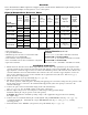
Eight (8) Output AL168 Reference Chart:
Altronix
Model Number
Output
Voltage
Total
Output
Current
(Power)
Number
of
Outputs
PTC
Protected
Outputs
Fuse
Protected
Outputs
Output
Current
(max
per
output)
Main Fuse
Ratings
on Board
115VAC
50/60Hz
Input
Current
AL168CB
16VAC 6 amp
8 x - 2.5 amp 10 amp/250V 0.9 amp
18VAC 5.5 amp
AL168175CB 16VAC 10 amp 8 x - 2.5 amp 15 amp/250V 1.45 amp
AL168300CB
16VAC 18 amp
8 x - 2.5 amp 15 amp/32V 2.7 amp
18VAC 16 amp
AL168300CBM
16VAC 18 amp
8 x - 2.5 amp 15 amp/32V 2.7 amp
18VAC 16 amp
AL168600CB
16VAC 40 amp
8 x - 6 amp
Two (2)
15 amp/32V
5.4 amp
18VAC 36 amp
•Surgesuppression.
•ACpowerLEDindicator.
•Illuminatedpowerdisconnectcircuitbreakerwith
manual reset (except AL168CB).
•Unitmaintainscamerasynchronization.
•Easeofinstallationsavestime&eliminatescostlylabor.
•Sparefusesincluded.
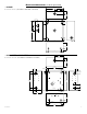
Enclosure Dimensions (H x W x D):
AL168CB:
8.5” x 7.5” x 3.5” (215.9mm x 190.5mm x 88.9mm)
AL168175CB and AL168300CBM:
8.5” x 7.5” x 3.75” (215.9mm x 190.5mm x 95.25mm)
AL168300CB and AL168600CB:
13.5” x 13” x 3.25” (342.9mm x 330.2mm x 82.55mm)
Specifications:
Installation Instructions:
1. Mountunitinthedesiredlocation.Markandpredrillholesinthewalltolineupwiththetoptwokeyholesinthe
enclosure. Install two upper fasteners and screws in the wall with the screw heads protruding. Place the enclosure’s
upperkeyholesoverthetwoupperscrews,levelandsecure.Markthepositionofthelowertwoholes.Removethe
enclosure.Drillthelowerholesandinstallthethreefasteners.Placetheenclosure’supperkeyholesoverthetwo
upperscrews.Installthetwolowerscrewsandmakesuretotightenallscrews(Enclosure Dimensions, pg. 7).
Secure enclosure to earth ground.
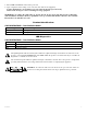
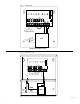
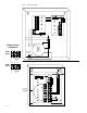
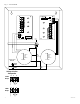
2. Turn OFF main switch (except AL168CB) (Figs. 2-5, pgs. 4-6).
3. All units are factory set for 16VAC operation.
For18VACoperation,adjustunitpriortomountingandapplyingpowerasfollows:Changethewirepositionsothat
theblackwire[18V]isconnectedtotheterminalmarked[P]andtheyellowwire[16V]isconnectedtothe
terminalmarked[S].
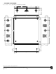
4. ConnectACpowertotheblackandwhiteflyingleadsofthetransformer(s)
(Figs. 1-5, pgs. 4-6).Use18AWGorlargerforallpowerconnections.
5. Measure output voltage before connecting devices. This helps avoiding potential damage.
Terminalsmarked[1P-8P]arepositiveofthesamepolarity.
CAUTION:Determinethemaximumoperatingvoltageoftheequipmentbeingpoweredbeforeadjusting
the output voltage.
6. Connectdevicestoterminalsmarked[1P-1Nthrough4P-4N]onPD4/PD4CBboard(Figs. 3 & 5, pgs. 5-6)
orterminalsmarked[1P-1Nthrough8P-8N]onPD8/PD8CBboard(Figs. 1, 2 & 4, pgs. 4-5),carefully
observing polarity.
7. Turnmainswitchtothe“RESET”(ON)position(exceptAL168CB)(Figs. 3-5, pgs. 5-6).