
Installation Instructions

Overview:
The AL176ULB is a power-limited power supply/charger that converts a 24VAC input into 12VDC or 24VDC output
(see specifications). It is intended for use in applications requiring UL Recognition for Access Control (UL294).
Specifications:
Power Supply Output Specifications:
Output VDC Jumper Max. Stand-by Load DC Max. Alarm Load DC Battery (optional)
12VDC Jumper Removed 1.75A 1.75A 12VDC
24VDC Jumper On 1.75A 1.75A 24VDC
Stand-by Specifications:
Output 4 hr. of Stand-by and 5 Minutes of Alarm
12VDC / 7 AH Battery
Stand-by = 1.25A
Alarm = 1.25A
24VDC / 7 AH Battery
Installation Instructions:
The AL176ULB should be installed in accordance with article 760 of The National Electrical Code or NFPA 72, as well
as all applicable Local Codes.
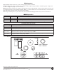
See Terminal Identification Chart on page 2 for a description of each terminal function.
1. Mount the AL176ULB in the desired location/enclosure.
2. Connect 24VAC/40VA transformer to the terminals marked [ XFMR INPUT ].
Use 18 AWG or larger for all power connections (Battery, AC input). Use 22 AWG to 18 AWG for power-
limited circuits (DC output, AC FAIL and LOW BAT supervisory relays).
Keep power-limited wiring separate from non power-limited wiring (115VAC / 60Hz Input, Battery Wires).
Minimum 0.25” spacing must be provided.
3. Set the AL176ULB to the desired DC output voltage by either removing/leaving jumper.
(see Power Supply Output Specifications).
4. Connect battery to the terminals [+ BAT -- ] as marked on the unit (battery leads included). Use two (2) 12VDC
batteries connected in series for 24VDC operation.
Note: For Access Control applications batteries are optional. When batteries are not used, a loss of AC will result in
the loss of output voltage. When the use of stand-by batteries is desired, they must be lead acid or gel type.
5. Measure output voltage before connecting devices. This helps avoiding potential damage.
6. Connect devices to be powered to the terminals marked [ + DC -- ] (Fig. 1).
7. Connect appropriate signaling notification devices to AC Fail and Low Bat supervisory relay outputs.
Note: To meet UL requirements, AC Supervisory outputs must be connected to the zone of Alarm Control Panel or
to a visual AC trouble indicator.
AL176ULB
Access Control Power Supply/Charger
Agency Listings:
• UL Recognized component for US and Canada.
Input:
• 28VAC, 56VA from UL Listed, Class 2 transformer.
Output:
• 12VDC or 24VDC selectable outputs.
• 1.75A supply current.
• Class 2 Rated power-limited output.
• PTC protected outputs, rated @ 2.5A.
• Filtered and electronically regulated output.
• Short circuit and thermal overload protection.
Battery Backup:
• Built-in charger for sealed lead acid or gel type batteries.
• Automatic switch over to stand-by battery when AC fails.
• Maximum charge current 0.4A.
Supervision:
• AC fail supervision (form “C” 1A @ 28VDC).
• Low battery supervision (form “C” 1A @ 28VDC).
Visual Indicators:
• AC input and DC output LED indicators.
Board Dimensions (W x L x D approx.):
3.1” x 5.3” x 1.4” (78.74mm x 134.62mm x 35.56mm).