
Installation Instructions User Manual
- 6 - M series
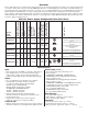
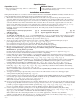
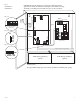
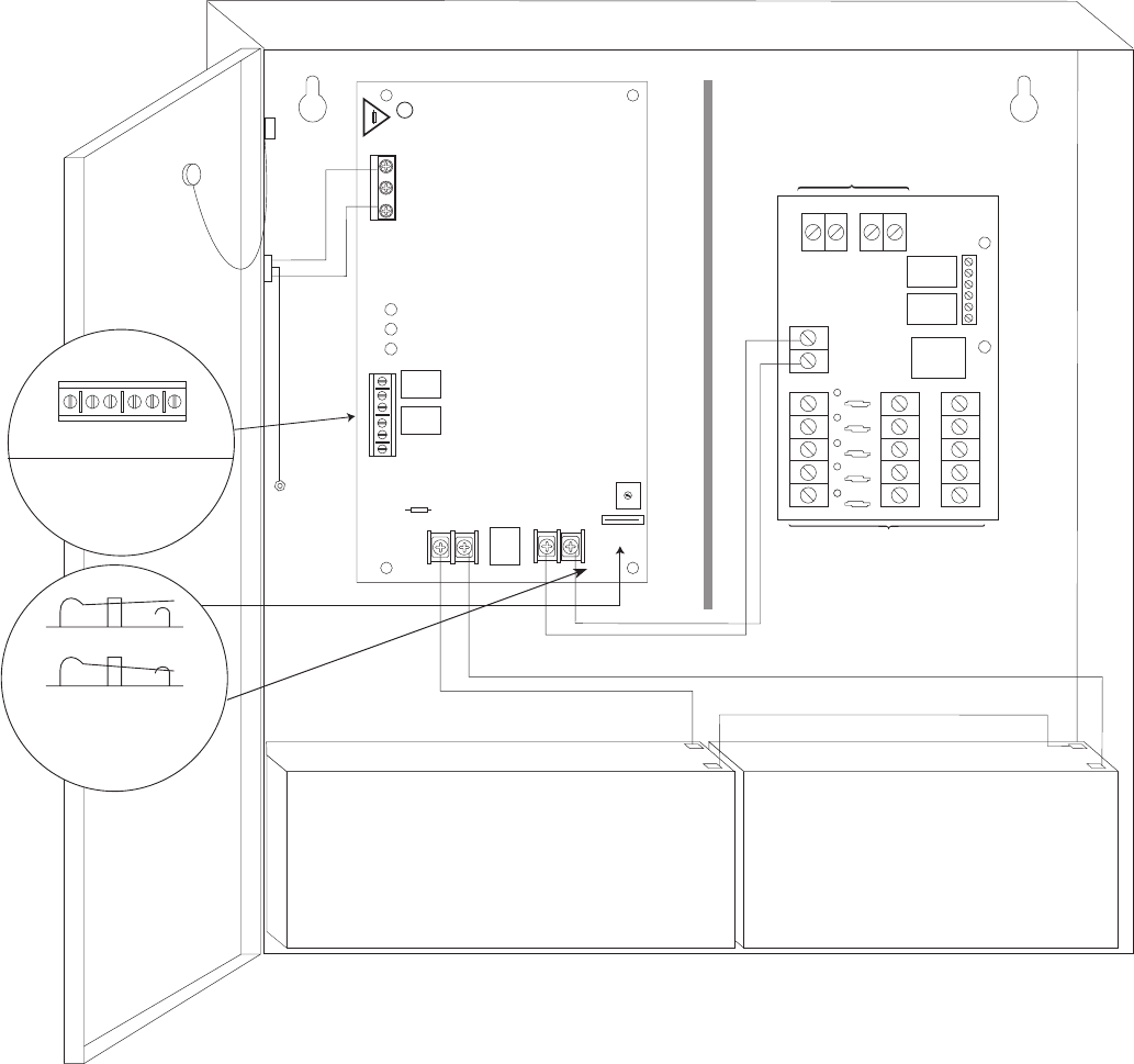
Fig. 2
AL600ULM
+ DC ---
BAT FAIL
NC C NO NC C NO
+ BAT ---
AC FAIL
LG N
5A 250V
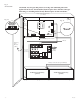
OPEN - 24V
CLOSED - 12V
SW1
DCAC BAT
Battery connection (non power limited)
Wire
Strap
(from
Enclosure
to Door)
115VAC
power mains
non-power
limited
Class 1
Divider
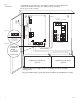
NC C NO
DRY OUTPUT
TRIGGER
LED
678910
POS (+) DC OUTPUT (STANDBY)
NC C NO
POWER FAIL
TRIGGER
12345
POS (+) DC OUTPUT (ALARM)
NEG1 NEG2 NEG3 NEG4 NEG5
-- DC INPUT +
NEG (-) INPUT POS (+)
DC Outputs to devices
(power limited)
Fire Alarm
Interface
non-power limited
Power Limited
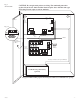
NC C NO NC C NO
AC FAIL
BAT FAIL
Battery & AC
Supervision Circuit
(power limited)
Switch Detail
OPEN SWITCH
CLOSED SWITCH
12VDC Rechargeable Battery
(optional)
12VDC Rechargeable Battery
(optional)
CAUTION: When power supply board is set for 12VDC use only one (1) 12VDC
stand-by battery.
Keep power limited wiring separate from non-power limited. Use minimum 0.25" spacing.
CAUTION: De-energize unit prior to servicing. For continued protection against risk of
electric shock and fire hazard replace fuse with the same type and rating.
Do not expose to rain or moisture.
Green
Lead
(ground)
Fig. 2a
Fig. 2b