
Installation Instructions


- 4 - ALTV1224DC Series Installation Guide
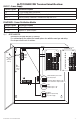
Door
CAUTION: De-energize unit prior to servicing.
For continued protection against fire hazard replace fuse with the same type and rating.
Do not expose unit to rain or moisture.
Wire Strap
(from
Enclosure
to Door)
115VAC
power
mains
Divider
Green
Flying
Lead
SW1
24VDC output - OFF
12VDC output - ON
OFF ON
3.5A 250V
common
outputs
protected
outputs
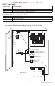
P
N
NPS
XFMR Input
12345678
9 10 11 12 13 14 15 16
NP
Used on PTC protected
ALTV1224DC1CB
P
N
NPS
XFMR Input
common
outputs
protected
outputs
12345678
9 10 11 12 13 14 15 16
NP
OFF - 24V
ON - 12V
ON
OFF - 24V
ON - 12V
ON
Trimpot
Adjusts output voltage
on power supply
Switch disables power mains
line voltage input.
If stand-by battery (batteries) are
connected the DC output remains on.
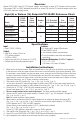
ALTV1224DC1/CB Terminal Identification:
OLS127 - Power Supply
Terminal Legend Function/Description
L, N 115VAC power mains connection.
– DC + 12VDC or 24VDC @ 4A total continuous output.
– BAT + Stand-by battery connections. Maximum charge rate 0.5A.
PD16W/PD16WCB - Power Distribution Module
Terminal Legend Function/Description
1P - 16P Positive DC power outputs.
1N - 16N Negative DC power outputs.
Fig. 2 - ALTV1224DC1/CB