
User Manual


ALTV248UL Series Installation Guide - 3 -
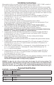
Installation Instructions:
Wiring methods shall be in accordance with the National Electrical Code/NFPA 70/NFPA 72/ANSI, and with all
local codes and authorities having jurisdiction. Product is intended for indoor use only.
1. Mount unit in the desired location. Mark and predrill holes in the wall to line up with the top two keyholes
in the enclosure. Install two upper fasteners and screws in the wall with the screw heads protruding. Place
the enclosure’s upper keyholes over the two upper screws, level and secure. Mark the position of the lower
two holes. Remove the enclosure. Drill the lower holes and install the three fasteners. Place the enclosure’s
upper keyholes over the two upper screws. Install the two lower screws and make sure to tighten all screws
(Enclosure Dimensions, Pg. 14-16). Secure enclosure to earth ground.
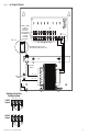
2. Set power switch on power distribution board marked [PD] to OFF position for models ALTV248UL or
ALTV248ULCB
(Fig. 1a, 2a, Pg. 4, 5). Set power disconnect circuit breaker to OFF position for all
other models
(Fig. 3a - 10a, Pg. 6-13).
3. All units are factory set for 24VAC operation.
For 28VAC operation adjust unit prior to mounting and applying power as follows:
Change the wire position so that the wire marked [28V] is connected to the terminal marked [P] and
the wire marked [24V] is connected to the terminal marked [S]
.
Note: ALTV248ULCB set for 28VAC operation is not Class 2 Rated, not power-limited.
4. Connect AC power to the black and white flying leads of the transformer(s)
(Fig. 1-10, Pg. 4-13),
secure green lead to earth ground. Use 18 AWG or larger for all power connections.
Keep power-limited (PTC protected outputs only) wiring separate from non power-limited wiring.
Minimum 0.25” spacing must be provided. Use separate knockouts.
5. Set power switch on power distribution board marked [PD] to ON position for models ALTV248UL or
ALTV248ULCB
(Fig. 1a, 2a, Pg. 4, 5). Set power disconnect circuit breaker to RESET (ON) position
for all other models
(Fig. 3a-10a, Pg. 6-13).
6. Measure output voltage before connecting devices. This helps avoiding potential damage.
Terminals marked [1P] - [8P] are of the same polarity.
CAUTION: Determine the maximum operating voltage of the equipment being powered before adjusting
the output voltage.
7. Set power switch on power distribution board marked [PD] to OFF position for models ALTV248UL or
ALTV248ULCB
(Fig. 1a, 2a, Pg. 4, 5). Set power disconnect circuit breaker to OFF position for all
other models
(Fig. 3a-10a, Pg. 6-13).
8. Connect devices to terminals marked [1P] - [1N] through [4P] - [4N] on PD4/PD4CB board (Fig. 9, 10,
Pg. 12, 13)
or terminals marked [1P] - [1N] through [8P] - [8N] on PD8/PD8CB board (Fig. 1-8,
Pg. 4-12
), carefully observing polarity.
9. Set power switch on power distribution board marked [PD] to ON position for models ALTV248UL or
ALTV248ULCB
(Fig. 1a, 2a, Pg. 4, 5). Set power disconnect circuit breaker to RESET (ON) position
for all other models
(Fig. 3a-10a, Pg. 6-13).
10. Green LED will illuminate when power is present.
11. Upon completion of wiring, secure enclosure door with screws (supplied). Installation of cam lock is optional.
Caution: Equipment to be installed/serviced by authorized/trained personnel only.
Shut branch circuit power before installing/servicing equipment.
WARNING: To reduce the risk of fire or electric shock, do not expose the unit to rain or moisture. This
installation should be made by qualified service personnel and should conform to the National Electrical
Code and all local codes. Use 75˚C or higher rated UL insulated wiring for connecting the unit to the mains.
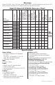
Replace fuses with the same type and rating (refer to Eight (8) Output ALTV248UL Reference Chart, pg. 2).
Terminal Identification:
PD4/PD4CB - Distribution Module
1P - 4P AC output.
1N - 4N AC output.
PD8/PD8CB - Distribution Module
1P - 8P AC output.
1N - 8N AC output.