
Installation Guide


eFlow4NB - 1 -
Installation Guide
eFlow4NB - Power Supply/Charger
Rev. EF4NB-111511
Overview:
The eFlow4NB power supply/charger converts a 120VAC / 60Hz input to a 12VDC or 24VDC @ 4A output.
Specifications:
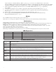
Stand-by Specifications:
Battery 4 hr. Stand-by and 15 min. Alarm 24 hr. Stand-by and 5 min. Alarm Access Control
7AH 0.4A/4A ----------------------- 15 Min
12AH 1A/4A 0.3A/4A 35 Min
40AH 4A/4A 1.2A/4A Over 4 Hours
65AH 4A/4A 1.5A/4A Over 4 Hours
Installation Instructions:
Wiring methods shall be in accordance with the National Electrical Code/NFPA 70/NFPA 72/ANSI, the Canadian
Electrical Code and with all local codes and authorities having jurisdiction. Product is intended for indoor use only.
1. Mount the eFlow4NB in desired location/enclosure.
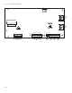
2. Set desired DC output voltage by setting SW1 to the appropriate position on the power supply board (Fig. 1i, pg. 3).
3. Connect unswitched AC power (120VAC 60Hz) to terminals marked [L, G, N] (Fig. 1a, pg. 3). Use 14 AWG or
larger for all power connections. Secure green wire lead to earth ground.
Keep power-limited wiring separate from non power-limited wiring (120VAC 60Hz Input, Battery Wires).
Minimum 0.25” spacing must be provided.
CAUTION: Do not touch exposed metal parts.
Shut branch circuit power before installing or servicing equipment.
There are no user serviceable parts inside. Refer installation and servicing to qualified service personnel.
4. Measure output voltage before connecting devices. This helps avoiding potential damage.
5. Connect devices to be powered to terminals marked [-- DC +] (Fig. 1h, pg. 3).
For auxiliary device connection this output will not be affected by Low Power Disconnect or Fire Alarm Interface.
Connect device to terminals marked [+ AUX -- ] (Fig. 1f, pg. 3).
6. For Access Control applications batteries are optional. When batteries are not used, a loss of AC will result in
the loss of output voltage. When the use of stand-by batteries is desired, they must be lead acid or gel type.
Agency Listings:
• UL Recognized component for: Access Control
System Units (UL 294), Power Supplies for use with
Burglar-Alarm Systems (UL 603), Power Supplies
for Fire Protective Signaling Systems (UL 1481).
• cUL Listed ULC-S318-96: Power Supply for Burglar
Alarm Systems.
Input Rating:
• Input 120VAC 60Hz, 3.5A.
Output:
• Power-limited output.
• 12VDC or 24VDC selectable output.
• 4A continuous supply current.
• Aux. Power-Limited output rated @ 1A (unswitched).
• Overvoltage protection.
• Filtered and electronically regulated outputs.
Battery Backup:
• Built-in charger for sealed lead acid or gel type batteries.
• Maximum charge current 1.54A.
Battery Backup (cont’d):
• Automatic switch over to stand-by battery when AC fails.
Transfer to stand-by battery power is instantaneous with
no interruption.
Fire Alarm Disconnect:
• Supervised Fire Alarm disconnect (latching or
non-latching) 10K EOL resistor. Operates on a normally
open (NO) or normally closed (NC) trigger.
Supervision:
• AC fail supervision (form “C” contacts).
• Battery fail and presence supervision (form “C” contacts).
• Low power shutdown. Shuts down DC output terminals
if battery voltage drops below 80% of nominal.
Prevents deep battery discharge.
Visual Indicators:
• Green AC Power LED indicates 120VAC present.
• AC input and DC output LED indicators.
Additional Features:
• Short circuit and overload protection.
Board Dimensions (approximate L x W x H):
7.5” x 4.6” x 1.75” (190.5 mm x 116.84 mm x 44.45 mm)