
Installation


- 4 - HubSat4Di
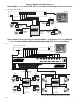
3. Set illuminated master power disconnect circuit breaker to the RESET (ON) position (Fig. 4a, pg. 6) power
LEDs (Green) of the HubSat4Di will illuminate when AC power is present (F
ig. 1e, pg. 4) and HubWayAv, HubWayDv
or HubWayDvi Video Balun/Combiner LEDs will illuminate indicating power is present (F
ig. 2b, 2d, pg. 6).
4.
Measure the output voltage at each Video Balun/Combiner (Figs. 2b, 2d, pg. 6) before making connections to
each camera to insure proper operation and avoid possible damage.
5. Set illuminated master power disconnect circuit breaker to the (OFF) position (Fig. 4a, pg. 6).
6
. Connect power outputs of HubWayAv, HubWayDv or HubWayDvi Video Balun/Combiners to power inputs
of cameras (Figs. 2a-2d, pg. 6). Polarity must be observed.
•
HubWayAv - Terminals marked [AC POWER] (Figs. 2a, 2b, pg. 6).
•
HubWayDv/HubWayDvi - Terminals marked [– 12VDC +] (Figs. 2c, 2d, pg. 6).
7
. Connect the terminals marked [+ DATA -- ] of HubWayAv, HubWayDv or HubWayDvi Video Balun/Combiners
to data input terminals of cameras for PTZ control (Figs. 2b-2d, pg. 6). Polarity must be observed.
When using fixed cameras disregard this step.
8
. Connect the BNC connector of HubWayAv, HubWayDv or HubWayDvi Video Balun/Combiners to the
BNC video outputs of cameras (Figs. 2b-2d, pg. 6).
9
. Set illuminated master power disconnect circuit breaker to the RESET (ON) position (Fig. 4a, pg. 6).
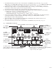
F
ig. 1 - HubSat4Di Circuit Board
1i - Channels 1-4:
CAT-5 or higher
structured cable
to cameras.
PVD1
V
IDEO1 VIDEO2 VIDEO3 VIDEO4
PVD2 PVD3 PVD4
+ DATA -
DATA 1-4 VIDEO 1-4
28VAC
2
4VAC
28VAC
2
4VAC
28VAC
2
4VAC
28VAC
2
4VAC
OFF
OFF
OFF
OFF
A
UX1 AUX2
A
UX3 AUX4
1e - LED(s) 1-4:
Power output
indicators.
1a - BNC
Connector: Video
in from remote
camera video
out to D
VR.
1g - Channels 1-4: Single CAT-5 or higher
structured cable out to HubWay8/16, HubWayLD8/16,
HubWayLDH8/16 enables transmission
of up to four (4) video signals.
1h - Data: CAT-5 or higher structured
cable to data port on HubWay8/16, HubWayLD8/16,
HubWayLDH8/16 or head end equipment (DVR).
1c - Power Terminals: 24VAC/28VAC power outputs.
1b - Output
PTCs: Protects
each output.
1f - Data:
RS422/RS485
input from head
end equipment
(D
VR) for PTZ
control.
1d - Output
Voltage Switches:
Selects
24V
AC/28VAC/OFF
for each output.