
Installation


HubSat4Di - 5 -
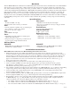
HubWayAv
*24VAC/28VAC *24VAC/28VAC
Use with AC cameras
Green
HubWayDv
12VDC *24VAC/28VAC
Use with DC cameras
Red
Altronix
Model
Number
HubWay Video Balun/Combiner Reference Chart:
Output Voltage
to camera
Input Voltage
from HubSat
Camera Type
Power LED
*Based on camera load and
structured cable length.
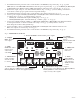
10. The power LEDs (Green) of the HubSat4Di will illuminate when AC power is present (Fig. 1e, pg. 4).
Note: If an
y of the power LEDs are not illuminated the cause may be due to the following:
a. AC mains fail.
b. Illuminated master power disconnect circuit breaker is tripped.
c. One or both primary in-line fuse(s) are blown.
Note: Replace fuse with same type and rating:
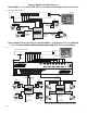
Primary in-line fuses are rated @ 3.5A/250V (Fig. 4b, pg. 6).
d.
An individual power output voltage switch is set to the OFF position (Fig. 1d, pg. 4).
e.
A PTC is tripped due to a short circuit or overload condition for one or more channels/power outputs.
To reset the PTC:
1. Set the voltage output selector switch for that corresponding channel to the OFF position. Switch must
remain in the OFF position for approximately 2 minutes in order for the PTC to reset (Fig. 1d, pg. 4).
2.
Eliminate the trouble condition (short circuit or overload).
3. Set the voltage output selector switch for either 24VAC or 28VAC (Fig. 1d, pg. 4).
Alternate 24VAC fixed camera hookup (Fig. 6a, pg. 7).
After completing steps 1-5 of Installation Instructions Remote Accessory Module for use with HubWay, HubWayLD or
HubW
ayLDH UTP Transceiver Hubs proceed with the following.
1. Set illuminated master power disconnect circuit breaker to the (OFF) position (Fig. 4a, pg. 6).
2.
Connect one end of the coaxial cable to the BNC connector marked [Video1] on HubSat4Di (Fig. 1a, pg. 4).
Connect the opposite end of the coaxial cab
le to the BNC video output of camera 1 (Fig. 6a, pg. 7).
3.
Set illuminated master power disconnect circuit breaker to the RESET (ON) position (Fig. 4a, pg. 6) measure the
output v
oltage at terminal pair marked [AUX1] on HubSat4Di to insure proper operation and avoid possible
damage (Fig. 1c, pg
. 4).
4. Connect the power output terminal pair marked [AUX1] on HubSat4Di to the power inputs of camera 1
(Fig. 1c, pg. 4). Repeat steps 1-3 for each additional camera [AUX2-4].
Primary
In-line Fuse