
HubWayLD8Di_16Di Installation

- 4 - HubWayLD Active Isolated Unit
1 2 3 4 CH 1-4 CH 5-8
28VAC
OFF
24VAC
+ DATA -
1-8
+ DATA -
9-16
5 6 7 8 9 10 11 12 CH 9-12
28VAC
OFF
24VAC
13 14 15 16 CH 13-16
AC POWER
16
PICTURE GAIN PICTURE GAIN PICTURE GAIN PICTURE GAIN PICTURE GAIN PICTURE GAIN PICTURE GAIN PICTURE GAIN PICTURE GAIN PICTURE GAIN PICTURE GAIN PICTURE GAIN PICTURE GAIN PICTURE GAIN PICTURE GAIN PICTURE GAIN
15 14 13 12 11 10 9 8 7 6 5 4 3 2 1
OFF
RESET
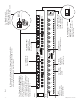
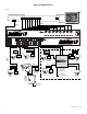
1a - Channels 1-8 (HubWayLD8i)
or Channels 1-16 (HubWayLD16i):
CAT-5 or higher structured cable to
Video/Balun Combiners at
cameras 1-8 or 1-16. When using an
optional HubSat4D any of the out-
puts can be utilized for the data
transmission to PTZ”s.
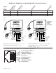
1f - BNC
Connector: Video
outputs to head end
equipment (DVR).
1d - Output voltage
switches: Selects
24VAC/28VAC/OFF
for each output.
1b - Channels 1-4, Channels 5-8, Channels 9-12 & Channels 13-16:
CAT-5 or higher structured cable from optional HubSat4D enables
video transmission from up to four (4) cameras.
1i - LED(s) 1-16:
Video signal indicators.
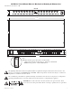
1j - IEC 320 Connector:
115VAC 60Hz/230VAC
50/60Hz (grounded
line cord included).
Fig. 1
1g - Picture:
Adjusts video
quality.
1h - Gain:
Regulates the
output video
and sync levels.
1e - Data: Removable
terminal blocks for RS422/
RS485 input from head end
equipment (DVR) for PTZ control.
+ --
Data input from
Head End
Equipment (DVR).
Top View
1k - Input Voltage Switch:
Selects 115VAC
60Hz/230VAC 50/60Hz
(switch is located on the left
side of the unit).
115VAC 220VAC
1c - LED(s) 1-16:
Power indicators.
Front
Rear