
Installation Guide

- 7 - MaxiFit11FE/13FE/33FE/35FE/37FE/55FE/75FE/77FE Expandable Power Systems
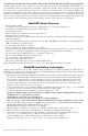
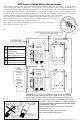
NEC Power-Limited Wiring Requirements:
Power-limited and non power-limited circuit wiring must remain separated in the cabinet. All power-limited
circuit wiring must remain at least 0.25” away from any non power-limited circuit wiring. Furthermore, all
power-limited circuit wiring and non power-limited circuit wiring must enter and exit the cabinet through differ-
ent conduits. One such example of this is shown below. Your specific application may require different conduit
knockouts to be used. Any conduit knockouts may be used. For power-limited applications use of conduit is
optional. All field wiring connections must be made employing suitable gauge CM or FPL
jacketed wire (or equivalent substitute). Optional UL Listed battery enclosure must be
mounted adjacent to the power supply via Class 1 wiring methods. For Canadian
installations use shielded wiring for all connections.
Note: Refer to wire handling drawing below for the proper way to install the
CM or FPL jacketed wire (Fig. 3b).
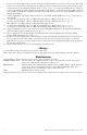
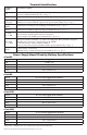
Fig. 3
A ACM8(CB), ACMS8(CB)
B
ACM4(CB),
LINQ8PD(CB),
PD4UL(CB), PD8UL(CB),
MOM5, PDS8(CB), VR6
C PD16W(CB)
D
NetWaySP3B, NetWay4EB,
NetWaySP4B, NetWaySP8B
Tamper Switch
To Access Control Panel or
UL Listed Reporting Device
Edge of
Enclosure
Enclosure
External
Jacketed
Shield
Incorrect Wire
Handling
Correct Wire
Handling
Pull back
external jacketed
shield approx. 1/2”.
Wire
Insulation
Solid Copper
Conductors
Tamper Switch
Optional
Rechargeable
Stand-by Battery
for UL294
Applications
Note:
12V batteries
are required for
ULC-S319
installations.
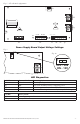
Input 120VAC, 60Hz
(non power-limited)
CAUTION: When power supply board is set for 12VDC use only one (1) 12VDC
stand-by battery. Connect red battery lead to the terminal marked [+ BAT] and
to the [positive (+)] terminal of the battery. Connect black battery lead to terminal
marked [BAT –] and to the [negative (–)] terminal of the battery.
Keep power-limited wiring separate from non power-limited.
Use minimum 0.25" spacing.
12AH Rechargeable batteries are the largest batteries that
can fit in this enclosure.
A UL listed external battery enclosure must be
used if using the 40AH or 65AH batteries.
Supervisory Connections, Aux. Outputs to Devices and
Fire Alarm Interface (power-limited)
NC C NO NC
C NO
AC FAIL BAT FAIL
TRIGGER
AC DCAC1
EOL NO GND
SUPERVISED RESET
+AUX-
- BAT +- DC +
L G N
A
B
C
D
A
B
C
Power
Supply/
Charger
NC C NO NC
C NO
AC FAIL BAT FAIL
TRIGGER
AC DCAC1
EOL NO GND
SUPERVISED RESET
+AUX-
- BAT +- DC +
L G N
Power
Supply/
Charger
DC Output
(non power-limited)
Battery
(non power-limited)
DC Output
(non power-limited)
Battery
(non power-limited)
Fig. 3b
Fig. 3a