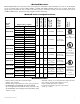
Series Expandable Power Systems Installation Guide Models Include: Maximal11E Maximal13E Maximal33E Maximal35E Maximal37E Maximal55E Maximal75E Maximal77E - Power Supply 1: 12VDC @ 4 amp or 24VDC @ 3 amp. - Power Supply 2: 12VDC @ 4 amp or 24VDC @ 3 amp. - Power Supply 1: 12VDC or 24VDC @ 6 amp. - Power Supply 2: 12VDC or 24VDC @ 6 amp. - Power Supply 1: 12VDC or 24VDC @ 6 amp. - Power Supply 2: 24VDC @ 10 amp. - Power Supply 1: 24VDC @ 10 amp. - Power Supply 2: 12VDC @ 10 amp.
Table of Contents: MaximalE Overview......................................................................................................... 3 MaximalE Series Configuration Chart............................................................................. 3 MaximalE Features........................................................................................................ 3-4 MaximalE Installation Instructions..................................................................................
MaximalE Overview: Maximal Expandable Power System provide system designers and installers with maximum power choices and the highest levels of versatility. They provide 12VDC, 24VDC, or 12VDC and 24VDC simultaneously via two (2) single output power supply/chargers. Includes AC fail, low battery and battery presence monitoring. Custom enclosure facilitates up to four (4) 12VDC/12AH batteries. All interconnecting equipment must be UL Listed.
MaximalE Features (cont’d): • Short circuit and thermal overload protection with auto reset. • AC input and DC output LED indicators. • AC fail supervision (form “C” contact). • Enclosure accommodates up to four (4) 12VDC/12AH batteries. • Enclosure dimensions: 27” x 19” x 6.25” (685.8mm x 482.6mm x 158.75mm). MaximalE Installation Instructions: Wiring methods shall be in accordance with the National Electrical Code/NFPA 70/ANSI, and with all local codes and authorities having jurisdiction.
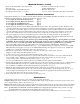
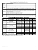
Power Supply Board Terminal Identification: Terminal Legend L, G, N + DC – AC FAIL NC, C, NO Function/Description Connect 115VAC 60Hz to these terminals: L to hot, N to neutral. Refer to Maximal Series Configuration Chart, pg. 3. Indicates loss of AC power. To meet with UL requirements it is mandatory to connect visual notification devices, connecting audible notification devices is optional. Relay normally energized when AC power is present. Contact rating 1 amp @ 28VDC.
Power Supply Board LED Diagnostics: Red (DC) ON ON OFF OFF Red (Bat) ON OFF LED Green (AC) ON OFF ON OFF Power Supply Status Normal operating condition. Loss of AC. Stand-by battery supplying power. No DC output. Short circuit or thermal overload condition. No DC output. Loss of AC. Discharged battery. Battery Status Normal operating condition. Battery fail/low battery. Power Supply Board Output Voltage Settings: Fig. 1 Fig. 1a AL400ULXB2 / AL600ULXB Power Supply Board Fig.
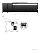
Fig. 2 + BAT --- Power Supply Board Fig. 2a --- DC + + DC --- Tamper Switch G BAT FAIL N Line NO C NC NO C NC Power Supply Board [DC] Terminal Layout for: AL1012ULXB AC FAIL + DC --- Neutral + BAT --- Power Supply Board 115VAC Input 60 Hz.
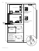
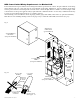
NEC Power-Limited Wiring Requirements for Maximal11E: Power-limited and non power-limited circuit wiring must remain separated in the cabinet. All power-limited circuit wiring must remain at least 0.25” away from any non power-limited circuit wiring. Furthermore, all power-limited circuit wiring and non power-limited circuit wiring must enter and exit the cabinet through different conduits. One such example of this is shown below. Your specific application may require different conduit knockouts to be used.
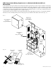
NEC Power-Limited Wiring Requirements for Maximal13E: Power-limited and non power-limited circuit wiring must remain separated in the cabinet. All power-limited circuit wiring must remain at least 0.25” away from any non power-limited circuit wiring. Furthermore, all power-limited circuit wiring and non power-limited circuit wiring must enter and exit the cabinet through different conduits. One such example of this is shown below. Your specific application may require different conduit knockouts to be used.
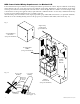
NEC Power-Limited Wiring Requirements for Maximal33E, Maximal35E and Maximal55E: Power-limited and non power-limited circuit wiring must remain separated in the cabinet. All power-limited circuit wiring must remain at least 0.25” away from any non power-limited circuit wiring. Furthermore, all power-limited circuit wiring and non power-limited circuit wiring must enter and exit the cabinet through different conduits. One such example of this is shown below.
NEC Power-Limited Wiring Requirements for Maximal37E and Maximal75E: Power-limited and non power-limited circuit wiring must remain separated in the cabinet. All power-limited circuit wiring must remain at least 0.25” away from any non power-limited circuit wiring. Furthermore, all power-limited circuit wiring and non power-limited circuit wiring must enter and exit the cabinet through different conduits. One such example of this is shown below.
NEC Power-Limited Wiring Requirements for Maximal77E: Power-limited and non power-limited circuit wiring must remain separated in the cabinet. All power-limited circuit wiring must remain at least 0.25” away from any non power-limited circuit wiring. Furthermore, all power-limited circuit wiring and non power-limited circuit wiring must enter and exit the cabinet through different conduits. One such example of this is shown below. Your specific application may require different conduit knockouts to be used.
Enclosure Dimensions (H x W x D approximate): 27” x 19” x 6.25” (685.8mm x 482.6mm x 158.75mm) 2” (50.8mm) 4” (101.6mm) 19” (482.6mm) 7” (177.8mm) 4” (101.6mm) 1.25” (31.75mm) 6.25” (158.75mm) 1.25” (31.75mm) 6.25” (158.75mm) 10.76” (273.3mm) 0.85” (21.6mm) 0.85” (21.6mm) 2.5” (63.5mm) 9.5” (241.3mm) 7” (177.8mm) 25.5” (647.7mm) 7.5” 27” (109.5mm) (685.8mm) 27” (685.8mm) 8.5” (215.9mm) 21” (533.4mm) 13.5” (342.9mm) 7” (177.8mm) 1.25” (31.75mm) 1.0” (25.4mm) 6.25” (158.75mm) 4.65” (118.
Notes: - 14 - Maximal Expandable Power Systems
Notes: Maximal Expandable Power Systems - 15 -
Notes: Altronix is not responsible for any typographical errors. 140 58th Street, Brooklyn, New York 11220 USA, 718-567-8181, fax: 718-567-9056 web site: www.altronix.com, e-mail: info@altronix.com, Lifetime Warranty, Made in U.S.A.