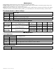
Rack Mount Series Installation Guide Models include: Maximal1RHD Maximal1RD - 12VDC @ 4 amp or 24VDC @ 3 amp. - Eight (8) PTC Protected Outputs. - 12VDC @ 4 amp or 24VDC @ 3 amp. - Sixteen (16) PTC Protected Outputs. Maximal3RHD Maximal3RD - 12VDC or 24VDC @ 6 amp. - Eight (8) PTC Protected Outputs. - 12VDC or 24VDC @ 6 amp. - Sixteen (16) PTC Protected Outputs. Maximal33RD - 12VDC and/or 24VDC @ 12 amp. - Sixteen (16) PTC Protected Outputs. Rev. 010708 More than just power.
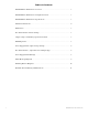
Table of Contents: MaximalD Rack Mount Series Overview........................................................................ 3 MaximalD Rack Mount Series Configuration Chart....................................................... 3 MaximalD Rack Mount Series Specifications................................................................. 3 Installation Instructions.................................................................................................... 4 Maintenance...............................
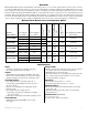
Overview: Maximal Rack Mount Series units distribute and switch power to access control systems and accessories. They convert a 115VAC 50/60Hz input into eight (8) or sixteen (16) independently controlled 12VDC and/or 24VDC PTC protected outputs. Outputs are activated by an normally open (NO) or normally closed (NC) dry trigger input from an Access Control System, Card Reader, Keypad, Push Button, PIR, etc.
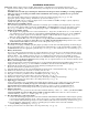
Installation Instructions: Important: Adjust output voltages and Fire Alarm Interface configuration before installing unit in the rack. 1. Separate bottom and top of the rack mount chassis by removing six (6) screws (Rack Mechanical Drawing & Dimensions, pg. 11). CAUTION: Do not touch exposed metal parts. Shut branch circuit power before installing or servicing equipment. There are no user serviceable parts inside. Refer installation and servicing to qualified service personnel. 2.
Maintenance: Unit should be tested at least once a year for the proper operation as follows: Output Voltage Test: Under normal load conditions the DC output voltage should be checked for proper voltage level (Output Voltage and Stand-by Specification Charts, pg. 5). Battery Test: Under normal load conditions check that the battery is fully charged, check specified voltage at the battery terminals and at the board terminals marked [– BAT +] to ensure that there is no break in the battery connection wires.
WARNING: To reduce the risk of fire or electric shock, do not expose the unit to rain or moisture. This installation should be made by qualified service personnel and should conform to the National Electrical Code and all local codes. The lightning flash with arrow head symbol within an equilateral triangle is intended to alert the user to the presence of an insulated DANGEROUS VOLTAGE within the products enclosure that may be of sufficient magnitude to constitute an electric shock.
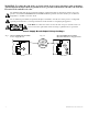
Fire Alarm Interface, Output Selection and Input Type: Fig. 2 FIRE ALARM INTERFACE 4 3 2 1 4 3 2 OUTPUT SELECT 1 ON INPUT TYPE Output Trigger LED’s 4 3 2 ON 1 4 3 2 ON SW3 1 ON ACM8R-S Fig. 2a 4 3 2 Fig.
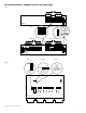
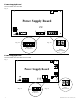
Power Supply Board Maximal1RHD, Maximal1RD Fig. 4 OPEN 24VDC CLOSED 12VDC Power Supply Board OFF AC DC NC NC + C NO ---C NO BAT Battery and AC Supervision Built-in Battery Charging NC C NO NC C NO LOW BAT N --- BAT + LOW BAT Fig. 4a G AC FAIL L AC FAIL ON 5A 250V --- DC + Fig. 4b --- BAT + Built-in Battery Charging Power Supply Board + DC --- OPEN - 24V CLOSED - 12V Maximal3RHD, Maximal3RD, Maximal33RD Fig.
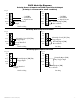
FACP Hook-Up Diagrams Polarity Reversal Input from FACP Signal Circuit Output (Polarity is referenced in alarm condition) Fig. 6 Fig. 7 GND GND IN8 5-30VDC -- from FACP + Signal Circuit 1 FACP 2 RESET GND Factory Installed Jumper IN8 1 FACP 2 RESET GND 5-30VDC -- from FACP + Signal Circuit Normally Open [NO] Reset Switch Latching Non-Latching Normally Closed Input from FACP Fig. 8 Fig.
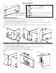
Mounting Options: Fig. 12 Mounting Hardware (Included): Remove center brace from rack mount chassis before proceeding with installation. A Two (2) mounting brackets. B Eight (8) flat head screws for mounting brackets. C Eight (8) pan head screws for faceplate. Rack Mount Installation 1. Remove center brace from rack mount chassis (Fig. 12, pg. 10). 2. Slide mounting brackets (A) into slots located on left and right side of rack enclosure (Fig. 13a).
Rack Mechanical Drawing & Dimensions 3.25”H x 19.125”W x 8.5”D Fig. 15 Fig. 15a Fig. 15b Fig.
Notes: Altronix is not responsible for any typographical errors. 140 58th Street, Brooklyn, New York 11220 USA, 718-567-8181, fax: 718-567-9056 web site: www.altronix.com, e-mail: info@altronix.com, Lifetime Warranty, Made in U.S.A.