
Installation Guide

NetWay8 / NetWay16 - 5 -
Installing a NetWay1512 Adapter for 12VDC IP Cameras up to 13W:
1. Mount NetWay1512 in proximity to IP camera
(Fig. 2, pg. 5). Affix one side of velcro (supplied)
to NetWay1512 and the place the second side of the
velcro in the desired location.
2. Connect structured cable from port marked [IN] on
NetWay1512 to any ports marked [OUT] of
NetWay8/NetWay16 (Fig. 2, pg. 5, Fig. 1a, pg. 4).
3. Connect structured cable from port marked [OUT]
on NetWay1512 to the IP camera (Fig. 2, pg. 5).
4. Connect 12VDC output from NetWay1512 terminals
marked [– 12VDC +] to the power input of the
IP camera (Fig. 2, pg. 5). Polarity must be observed.
5. Power LED indicator will illuminate on NetWay1512
under normal conditions (Fig. 2, pg. 5).
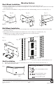
Installing a NetWay3012 Adapter for 12VDC IP PTZ up to 25W:
1. Mount NetWay3012 in proximity to IP camera
utilizing mounting hole (Fig. 3, pg. 5). Use a proper
fastener and/or wall anchor when securing
NetWay3012 to the wall.
2. Connect structured cable from port marked [IN] on
NetWay3012 to ports marked [OUT] of NetWay8/
NetWay16 (Fig. 3, pg. 5, Fig. 1a, pg. 4).
3. Connect structured cable from port marked [OUT] on
NetWay3012 to the IP fixed or PTZ camera
(Fig. 3, pg. 5).
4. Connect 12VDC output from NetWay3012 terminals
marked [+ 12VDC – ] to the power input of the
IP camera (Fig. 3, pg. 4). Polarity must be observed.
5. Power LED indicator will illuminate on NetWay3012
under normal conditions (Fig. 3, pg. 5).
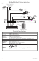
Installing a NetWayXT/NetWayXTX Repeater Module:
NetWayXT will work only with PoE devices.
NetWayXTX will work with PoE/PoE+ devices.
1. Mount NetWayXT/NetWayXTX in desired location
utilizing the mounting hole (Fig. 4, pg. 5). Use a
proper fastener and/or wall anchor when securing
NetWayXT/NetWayXTX to the wall.
2. Connect structured cable from port marked [OUT]
on NetWay to port marked [IN] on the NetWayXT/
NetWayXTX (Fig. 4, pg. 5, Fig. 1a, pg. 4).
3. Connect structured cable from port marked [OUT]
on NetWayXT/NetWayXTX to the PoE/PoE+
camera/edge device or next NetWayXT/
NetWayXTX repeater (Fig. 4, pg. 5).
4. Port status LEDs will illuminate on NetWayXT/
NetWayXTX indicating the port is operational
(refer to LED Definitions).
5. Power LED will illuminate indicating 12VDC output.
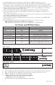
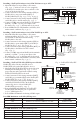
Port LED Definitions for NetWayXT Repeater:
Status Green LED Yellow LED
OFF Indicates it is connected as 10Base-T or no link. Indicates no link.
ON Indicates it is connected as 100Base-TX. Indicates a link.
Blinking – Indicates activity.
Port LED Definitions for NetWayXTX Repeater:
Status PoE/PoE+ Output LED PoE/PoE+ Input LED Yellow LED
OFF No PoE/PoE+ Output No PoE/PoE+ Input Indicates no link.
ON Normal PoE/PoE+ Output PoE/PoE+ Input Indicates a link.
Blinking – – Indicates activity.
NetwayXT
Repeater
www.altronix.com
IN
OUT
Power
Power
LED
Structured Cable
from NetWay8/16
Structured
Cable from
NetWay8/16
Structured Cable
to IP Camera/Edge Device
or next NetWayXT
PoE/PoE+
Output LED
Structured
Cable to
PoE/PoE+
Camera/Device or
next NetWayXTX
Port Status
LEDs
PoE/PoE+
Input
LED
NetWayXT
NetWayXTX
www.altronix.com
IN
OUT
Netway1512
Adapter
12VDC
--- Output +
-- +
12VDC
Output
Structured
Cable from
NetWay
Structured Cable
from IP Camera/Device
Power
LED
www.altronix.com
IN
OUT
Netway3012
Adapter
12VDC
+ Output ---
Power LED
12VDC
Power to
Camera
--
+
Structured Cable
from IP Camera
I.T.E. 43KC
Structured Cable
from NetWay8,
NetWay8M, NetWay16
or NetWay16M
Fig. 2 - NetWay1512
Fig. 3 - NetWay3012
Fig. 4 - NetWayXT/NetWayXTX