Power over the Ethernet Installation Guide Models Include: NetWaySP4PX - 4-port Ethernet to Fiber Media Converter with Integral Power Supply/Charger for Composite Fiber (Powered) Cable DOC#: NETSPX Rev. 032620 More than just power.
Table of Contents: Overview. . . . . . . . . . . . . . . . . . . . . . . . . . . . . . . . . . . . . . . . . . . . . . . . . . . . . . . . . . . . . . . . . . . . . . . . . . . . . . . . . . . . . . . . . . . . . . . . . pg. 3 Features. . . . . . . . . . . . . . . . . . . . . . . . . . . . . . . . . . . . . . . . . . . . . . . . . . . . . . . . . . . . .
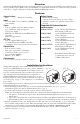
Overview: Altronix NetWaySP4PX Media Converter with Integral Power, provides four (4) 1Gb SFP ports and four (4) ports for up to 120W per port (480W total) to be transmitted over single/multi-mode fiber or composite cable (powered) cable (fiber + copper combined) to NetWay Spectrum PoE Hardened Switches. Features: Agency Listings: • CE European Conformity. Input: • 115VAC, 60Hz, 5.5A or 230VAC, 50/60Hz, 3A. (auto-ranging) Power: • Four (4) 56VDC non power-limited outputs up to 120W max.
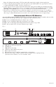
Note: All cabling and wire must be UL Listed and/or Recognized wire suitable for their application. 5. Connect Composite (Powered) Fiber cable: fiber portion to port marked [SFP 1-4], copper portion connects to output marked [OUT 56VDC, 1-4] (Fig. 2b & 2d, pg. 4). 6.
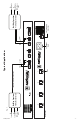
NetWaySP4PX -5- Rear Panel Front Panel WiFi Access Point IP Camera/Device IP Camera/Device Fig.
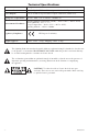
Technical Specifications: Parameter Number of Ports Description Four (4) Gigabit SFP Ports. Four (4) ports 10/100/1000Mbps. Power Outputs Four (4) 56VDC non power-limited outputs 120W max (480W total). Input power requirements 115VAC, 60Hz, 5.5A or 230VAC, 50/60Hz, 3A. Operating Ambient Temperature (120W): – 40ºC to 50ºC (– 40ºF to 122ºF) Relative Humidity: 85%, +/– 5% Environmental Conditions Storage Temperature: – 40ºC to 85ºC (– 40ºF to 185ºF). Operating Altitude: – 304.8 to 2,000m.
Notes: NetWaySP4PX -7-
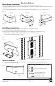
Rack Mount Installation Mounting Options: 1. Remove and discard factory installed screws from both sides of rack chassis (Fig. 4a). 2. Install mounting brackets (A) on the left and right side of rack chassis using the four (4) flat head screws (B) (included) (Fig. 4b). 3. Place unit into desired EIA 19” rack position and secure with mounting screws (not included) (Fig. 4c). Fig. 4 Fig. 4a Fig. 4b Top Fig. 4c Top Top Front Left Front Left Front Left B Remove A Wall Mount Installation 1.