
Installation Instructions


- 2 - SMP1024Xseries
Overview:
These units convert a 115VAC 60Hz input into a regulated 24VDC @ 10 amp continuous supply current
(see specifications).
SMP1024X Series Power Supply Configuration Reference Chart:
Altronix
Model Number
Accessory Power
Distribution
Module(s)
Number of
Outputs
Fused Outputs
PTC Outputs
Individual
Output Rating
Supervised
115VAC / 60Hz
Input Current
(amp)
24VDC Total
Output Current
(amp)
SMP10C24X
- 1 - - - - 2.7 amp 10 amp
SMP10PMC24X
- 1 - - -
P
2.7 amp 10 amp
SMP10PM24P4
PD4 4
P
- 3.5 amp
P
2.7 amp 10 amp
SMP10PM24P4CB
PD4CB 4 -
P
2.5 amp
P
2.7 amp 10 amp
SMP10PM24P8
PD8 8
P
- 3.5 amp
P
2.7 amp 10 amp
SMP10PM24P8CB
PD8CB 8 -
P
2.5 amp
P
2.7 amp 10 amp
SMP10PM24P16
PD16W 16
P
- 3.5 amp
P
2.7 amp 10 amp
SMP10PM24P16CB
PD16WCB 16 -
P
2.5 amp
P
2.7 amp 10 amp
Specifications:
Installation Instructions:
Wiring methods shall be in accordance with the National Electrical Code/NFPA 70/NFPA 72/ANSI, and with all local
codes and authorities having jurisdiction. Product is intended for indoor use only.
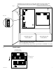
1. Mount unit in the desired location. Mark and predrill holes in the wall to line up with the top two keyholes in the
enclosure. Install two upper fasteners and screws in the wall with the screw heads protruding. Place the enclosure’s
upper keyholes over the two upper screws, level and secure. Mark the position of the lower two holes. Remove the
enclosure. Drill the lower holes and install three fasteners. Place the enclosure’s upper keyholes over the two
upper screws. Install the two lower screws and make sure to tighten all screws (Enclosure Dimensions, pgs. 6).
Secure enclosure to earth ground.
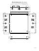
2. Connect AC power to the terminals marked [L & N], connect ground to the terminal marked [G] (if used),
(Fig. 1, pg. 4 or Fig. 4, pg. 5). Use 18 AWG or larger for all power connections (Battery, DC output).
Keep power-limited wiring separate from non power-limited wiring (115VAC / 60Hz Input, Battery Wires).
Minimum 0.25” spacing must be provided.
CAUTION: Do not touch exposed metal parts. Shut branch circuit power before installing or servicing equipment.
There are no user serviceable parts inside. Refer installation and servicing to qualified service personnel.
3. Measure output voltage before connecting devices. This helps avoiding potential damage.
Input:
• Input115VAC,60Hz,2.7amp.
Output:
• 24VDCoutput.
• 10ampsupplycurrent.
• Filteredandelectronicallyregulatedoutputs.
• Shortcircuitandthermaloverloadprotection.
Battery Backup:
• Built-inchargerforsealedleadacidor
gel type batteries.
• Maximumchargecurrent0.7amp.
• Zerovoltagedropwhenswitchingover
to battery backup.
Supervision:
• ACfailsupervision(form“C”contacts).
• Batterypresenceandlowbatterysupervision
(form“C”contacts).
Visual Indicators:
• ACinputandDCoutputLEDindicators.
Electrical:
• Operatingtemperature:0ºCto49ºCambient.
• BTU/Hr.:122.84BTU/Hr.
• SystemACinputVArequirement:310.5VA.
Mechanical:
• EnclosureDimensions(HxWxDapprox.):
13.5”x13”x3.25”(342.9mmx330.2mmx82.55mm)
- Accommodates up to two (2)12VDC/7AH batteries.