
Installation Instructions


SMP1024Xseries - 5 -
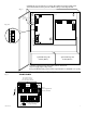
LOW BAT
NC C NO NC C NO
OFF ON
5A 250V
AC FAIL
--- BAT + --- DC +
15
AC DC
Door
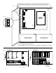
CAUTION: De-energize unit prior to servicing. For continued protection against risk of
electric shock and fire hazard replace fuse with the same type and rating 5A, 250V.
Green
Lead
Wire Strap
(from Enclosure
to Door)
115 power
mains
Class 1
Divider
Keep power-limited wiring separate from non power-limited. Use minimum 0.25" spacing.
CAUTION: Optional rechargeable stand-by batteries must match
the power supply output voltage setting.
Optional Rechargeable
Stand-by Battery
Optional Rechargeable
Stand-by Battery
Fig. 4
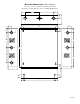
Fig. 4a
LOW BAT
NC C NO NC C NO
OFF ON
5A 250V
AC FAIL
--- BAT + --- DC +
15
AC DC
Power
Distribution
Module
Door
CAUTION: De-energize unit prior to servicing. For continued protection against risk of
electric shock and fire hazard replace fuse with the same type and rating 5A, 250V.
Green
Lead
Battery connection
Wire Strap
(from Enclosure
to Door)
115 power
mains
Class 1
Divider
12VDC Rechargeable Battery
(optional)
12VDC Rechargeable Battery
(optional)
3.5A 250V
For continuous protection against
risk of fire replace fuses with
same type and rating.
common
outputs
protected
outputs
P
N
NPS
XFMR Input
12345678
9 10 11 12 13 14 15 16
NP
DC Output to devices
1P-16P Power Outputs,
1N-16N Common Outputs
From
Power Supply Boar
d
(Factory Installed)
Used
on PTC
Models
Power Distribution Module(s):
Fig. 5
PD16W/PD16WCB