
Installation Instructions


Power Supply Voltage Output Specifications: *
Output VDC Switch Position Max. Load DC
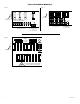
12VDC SW1 - Closed (Fig. 1b, pg. 3) 4 amp
24VDC SW1 - Open (Fig. 1b, pg. 3) 4 amp
*Specified at 25˚ C ambient.
Installation Instructions:
The unit should be installed in accordance with The National Electrical Code and all applicable Local Regulations.
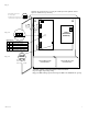
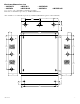
1. Mount the unit in the desired location.
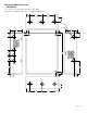
2. Set SW1 on the power supply board to the desired DC output voltage
(Power Supply Voltage Output Specification Chart).
3. Connect AC power to the terminals marked [L & N].
Use 18 AWG or larger for all power connections (Battery, DC output).
Use 22 AWG to 18 AWG for power-limited circuits (AC Fail/Low Battery reporting).
Keep power-limited wiring separate from non power-limited wiring (115/230VAC / 60Hz Input, Battery Wires).
Minimum 0.25” spacing must be provided.
CAUTION: Do not touch exposed metal parts. Shut branch circuit power before installing or servicing equipment.
There are no user serviceable parts inside. Refer installation and servicing to qualified service personnel.
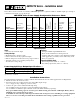
SMP5CTX Series Power Supply Configuration Reference Chart:
Altronix
Model Number
Accessory
Power
Distribution
Module(s)
Number
of
Outputs
Fused
Outputs
PTC
Outputs
Individual
Output
Rating (amp)
Supervised
115VAC/
230VAC
Input
Current
(amp)
12/24VDC
Total
Output
Current
(amp)
SMP5CTX
- 1 - - - - 0.95 / 0.5 4
SMP5PMCTX
- 1 - - - x 0.95 / 0.5 4
SMP5PMCTXX
- 1 - - - x 0.95 / 0.5 4
SMP5PMP4
PD4 4 x - 3.5 x 0.95 / 0.5 4
SMP5PMP4CB
PD4CB 4 - x 2.5 x 0.95 / 0.5 4
SMP5PMP8
PD8 8 x - 3.5 x 0.95 / 0.5 4
SMP5PMP8CB
PD8CB 8 - x 2.5 x 0.95 / 0.5 4
SMP5PMP16
PD16W 16 x - 3.5 x 0.95 / 0.5 4
SMP5PMP16CB
PD16WCB 16 - x 2.5 x 0.95 / 0.5 4
Specifications:
Input:
• Universal115/230VACinput.
Battery Backup:
• Maximumchargecurrent0.5amp.
• Filteredandelectronicallyregulatedoutputs.
• Built-inchargerforsealedleadacidorgeltypebatteries.
• Automaticswitchovertostand-bybatterywhen
AC fails (zero voltage drop).
Features:
• ACinputandDCoutputLEDindicators.
• Shortcircuitandthermaloverloadprotection.
• Completewithpowersupply,powerdistributionmodule
(when applicable), enclosure, cam lock & battery leads.
• Poweron-offswitch.
Supervised Models Only:
• ACfailsupervision(form“C”contacts).
• Lowbatterysupervision(form“C”contacts).
SMP5CTX Series - Installation Guide
Overview:
These units convert a 115VAC or 230VAC, 50Hz/60Hz input into a regulated 12VDC or 24VDC output up to 4 amps of
continuous load current (see specifications).
SMP5CTX Series - 1 -