
Installation Instructions

Power Supply Voltage Output Specifications:*
Output VDC Switch Position Max. Load DC
12VDC SW1 - ON (Fig. 4b, pg. 3) 6 amp
24VDC SW1 - OFF (Fig. 4b, pg. 3) 6 amp
*Specified at 25˚ C ambient.
Installation Instructions:
The unit should be installed in accordance with The National Electrical Code and all applicable Local Regulations.
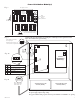
1. Mount unit in the desired location. Mark and predrill holes in the wall to line up with the top two keyholes in the
enclosure. Install two upper fasteners and screws in the wall with the screw heads protruding. Place the enclosure’s
upper keyholes over the two upper screws; level and secure. Mark the position of the lower two holes. Remove the
enclosure. Drill the lower holes and install the three fasteners. Place the enclosure’s upper keyholes over the two
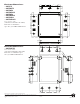
upper screws. Install the two lower screws and make sure to tighten all screws (Enclosure Dimensions, pg. 4).
Secure enclosure to earth ground.
2. Set SW1 on the power supply board to the desired DC output voltage (Power Supply Voltage Output Specification Chart).
3. Connect AC power to the terminals marked [L & N], (Fig. 4, pg. 3).
Keep power-limited wiring separate from non power-limited wiring (115VAC / 60Hz Input, Battery Wires).
Minimum 0.25” spacing must be provided.
CAUTION: Do not touch exposed metal parts. Shut branch circuit power before installing or servicing equipment.
There are no user serviceable parts inside. Refer installation and servicing to qualified service personnel.
4. Measure output voltage before connecting devices. This helps avoiding potential damage.
5. Connect devices to be powered:
a. For Power Supply Board: connect to the terminals marked [– DC + ].
b. For Power Distribution Module(s): connect devices to be powered to the terminal pairs 1 to 4 marked
[1P & 1N] through [4P & 4N] (Fig. 1, pg. 2) on PD4/CB board, terminal pairs 1 to 8 marked
Specifications:
SMP7CTX Series - Installation Guide
Overview:
SMP7CTX Series units convert a 115VAC / 60Hz input into a regulated 12VDC or 24VDC output up to 6 amp of
continuous load current (see specifications).
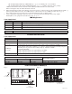
SMP7CTX Series Power Supply Configuration Reference Chart:
Altronix
Model Number
Accessory
Power
Distribution
Module(s)
Number
of
Outputs
Fused
Outputs
PTC
Outputs
Individual
Output
Rating
(amp) Supervised
115VAC
60Hz
Input Current
(amp)
12/24VDC
Total Output
Current
(amp)
SMP7CTX
- 1 - - - - 2.5 6
SMP7PMCTX
- 1 - - - x 2.5 6
SMP7PMCTXX
- 1 - - - x 2.5 6
SMP7PMP4
PD4 4 x - 3.5 x 2.5 6
SMP7PMP4CB
PD4CB 4 - x 2.5 x 2.5 6
SMP7PMP8
PD8 8 x - 3.5 x 2.5 6
SMP7PMP8CB
PD8CB 8 - x 2.5 x 2.5 6
SMP7PMP16
PD16W 16 x - 3.5 x 2.5 6
SMP7PMP16CB
PD16WCB 16 - x 2.5 x 2.5 6
For a red enclosure add an “R” suffix to the part # e.g. SMP7CTXR
Battery Backup:
• Maximum charge current 0.7 amp.
• Filtered and electronically regulated outputs.
• Built-in charger for sealed lead acid or gel type batteries.
• Automatic switch over to stand-by battery when
AC fails (zero voltage drop).
Features:
• AC input and DC output LED indicators.
Features (cont’d):
• Short circuit and thermal overload protection.
• Complete with power supply, power distribution module
(when applicable), enclosure, cam lock, and battery leads.
• Power On/Off switch.
Supervised Models Only:
• AC fail supervision (form “C” contacts).
• Low battery supervision (form “C” contacts).
SMP7CTX Series - 1 -