
Installation Instructions

INPUT
LED
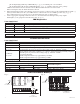
PD4
POWER DISTRIBUTING UNIT
ALTRONIX CORP.
BROOKLYN, NY 11220
MADE IN USA
1P, 2P, 3P, 4P = FUSED OUTPUTS
1N, 2N, 3N, 4N = COMMON OUTPUTS
F1
F1
F2 F3 F4
COMMON POWER OUTPUTS
1P
1N
2P
2N
3P
3N
4P
4N
DC Output to devices
From Power Supply
Board
(Factory Installed)
Used on
PTC Models
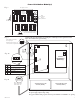
PD8
N
COMMON POWER OUTPUTS
P
FUSED POWER OUTPUTS
1 2 3 4 5 6 7 8
1
ALTRONIX CORP. MADE IN USA
BROOKLYN, NY 11220
D1
INPUT
R1
LED
DC Output to devices
From Power Supply
Board
(Factory Installed)
Used on
PTC Models
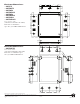
[1P & 1N] through [8P & 8N] on PD8/CB (Fig. 2, pg. 2) or terminal pairs 1 to 16 marked
[1P & 1N] through [16P & 16N] on PD16W/CB (Fig. 3, pg. 3), carefully observing correct polarity.
*Note: Power switch is used to disconnect the L (HOT) terminal from the rest of the board.
When servicing the unit, AC mains should be removed.
6. When using stand-by batteries, they must be lead acid or gel type. Connect battery to the terminals marked [– BAT +]
(battery leads included). Use two (2) 12VDC batteries connected in series for 24VDC operation (Fig. 4, pg. 3).
Note: When batteries are not used, a loss of AC will result in the loss of output voltage.
7. Connect appropriate signaling notification devices to the AC Fail & Low Bat supervisory relay outputs
marked [NC, C, NO] (supervised models only) (Fig. 4a, pg. 3).
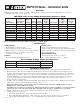
LED Diagnostics:
Power Supply Board
Red (DC) Green (AC) Power Supply Status
ON ON Normal operating condition.
ON OFF Loss of AC. Stand-by battery supplying power.
OFF ON No DC output.
OFF OFF Loss of AC. Discharged or no stand-by battery. No DC output.
Power Distribution Module
Green Power Distribution Module Status
ON Normal operating condition.
Terminal Identification:
Power Supply Board
Terminal Legend Function/Description
L, G, N Connect 115VAC to these terminals: L to Hot, N to Neutral.
--- DC + 12VDC / 24VDC @ 6 amp continuous output.
AC FAIL
NC, C, NO
Used to notify loss of AC power, e.g. connect to audible device or alarm panel. Relay normally
energized when AC power is present. Contact rating 1 amp @ 120VAC / 28VDC.
Low Battery
NC, C, NO
Used to indicate low battery condition, e.g. connect to alarm panel. Relay normally energized
when DC power is present. Contact rating 1 amp @ 120VAC / 28VDC.
Low battery threshold:
12VDC output threshold set @ approximately 10.5VDC,
24VDC output threshold set @ approximately 21VDC.
--- BAT + Stand-by battery connections. Maximum charge rate 0.7 amp.
Power Distribution Module
Terminal Legend
Function/Description
PD4/PD4CB PD8/PD8CB PD16W/PD16WCB
1P to 4P 1P to 8P 1P to 16P Positive DC power outputs
1N to 4N 1N to 8N 1N to 16N Negative DC power outputs
Fig. 1 Fig. 2
Power Distribution Module(s):
- 2 - SMP7CTX Series