StrikeIt4 Low Current Locking Device Power Controller Installation Guide Rev. 050919 More than just power.
Overview: Altronix StrikeIt4 will operate up to two (2) low current lock hardware devices simultaneously. It is designed to operate motorized electric latch retraction exit devices, electric strikes, mag-locks, electric mortise and cylindrical locksets, etc. Each lock output has an adjustable re-lock delay timer. It will control a pair of doors simultaneously, or independently control two single door leafs.
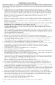
Installation Instructions: Wiring methods shall be in accordance with the National Electrical Code/NFPA 70/NFPA 72/ANSI, and with all local codes and authorities having jurisdiction. Product is intended for indoor use only. For Canadian installations shielded wiring of appropriate gauge must be used. Unit is to be serviced by authorized personnel and de-energized prior to opening. 1. Mount unit in desired location within protected premises (Maximum Wiring Distance, pg. 5).
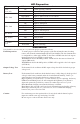
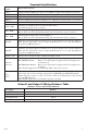
LED Diagnostics: LED Power Green (AC) OUT1 - Red OUT2 - Red FAI - Green BAT Trouble Red AC Trouble Green LED Status On Off On Rapid Blink Slow Blink Off On Rapid Blink Slow Blink Off On Off Off Slow Blink Off Slow blink Panic Device Power Controller Status Normal operating condition. Loss of AC. Output 1 - Energized. Output 1 - Short circuit or over-current. Output 1 - Open circuit Output 1 - De-energized. Output 2 - Energized. Output 2 - Short circuit or over-current.
Terminal Identification: Terminal Legend Function/Description – 24V + – 12V + – BAT + + OUT 1 – + OUT 2 – 24VDC Auxiliary Output @ 0.8A. 19.8-26.4VDC for applications with battery back-up. 12VDC Auxiliary Output @ 0.5A. 24VDC Stand-by Battery Connection (Two (2) 12VDC batteries wired in series). Connect 24VDC Low Current Lock Device # 1. Note: Load connected not to exceed 1A. Connect 24VDC Low Current Lock Device # 2. Note: Load connected not to exceed 1A.
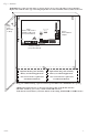
Fig. 1 115VAC/ 230VAC --- 5A 250V 12VDC G N --- Risk of Fire, Replace Fuses As Marked + 12VDC --- BAT + Rechargeable Batteries + L 5A 250V OUT2 Timer FSE IND 0.
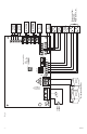
Fig. 2 - StrikeIt4 AC 5A 250V L G N --- BAT + Class 2 Power-Limited Outputs GND INP1 GND INP2 GND FACP OUT2 Timer OUT1 Timer ON FSE IND 0.5S DIS 5A 250V C NC TROUBLE -- 24V + FS SEQ 1S 24V + OUT1 --- OUT1 OUT2 FAI BAT AC Supervisory LEDs Battery Test + OUT2 --- Input 115VAC, 60Hz, 2.5A or 230VAC, 50Hz, 1.
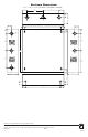
Enclosure Dimensions: 13.5” x 13” x 3.25” (342.9mm x 330.2mm x 82.6mm) 1.40” (36mm) 4.85” (123mm) 4.85” (123mm) 1.40” (36mm) 1.20” (31mm) 3.25” (83mm) 1.20” (31mm) 0.75” (19mm) 12.5” (318mm) 11.0” (279mm) 1.20” (31mm) 0.75” (19mm) 0.9375” (24mm) 1.40” (36mm) 1.40” (36mm) 5.10” (130mm) 5.10” (130mm) 13.0” (330mm) 5.10” (130mm) 6.5625” (167mm) 0.9375” (24mm) 3.25” (83mm) 3.25” (83mm) 3.25” (83mm) 1.0” (25mm) 1.0” (25mm) 1.0” (25mm) 10.5” (267mm) 1.