
Installation Guide


- 4 - T1MK Kits
Altronix
eFlow4NB
– DC +– BAT +
TRG
TRIGGER
INPUT
ACM4
ACCESS POWER
CONTROLLER
LED1 LED2 LED3 LED4
MAIN
OUTPUT 1
NC C NO COM NC C NO COM NC C NO COM NC C NO COM
OUTPUT 2 OUTPUT 3
IN GND
1
IN GND
2
IN GND
3
IN GND
4
OUTPUT 4
-- +
CONTROL
-- +
POWER
+INP- T +RET-
INTERFACE
NO C NC
FACP
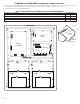
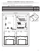
Altronix ACM4(CB)
Altronix PDS8(CB)
+ INP1
--
DM1 +
OFF
IN1
IN2
Out1
<
1 off 2
>
DM1 +
DM2 +
DM2 +
Common (--- )
Common (--- )
+ INP2
--
IN2 Fuse
IN1 Fuse
Common Power Outputs (NEG)
N
P
OUT1 OUT2 OUT3 OUT4 OUT5 OUT6 OUT7 OUT8
1 2 3 4 5 6 7 8
Out2
<
1 off 2
>
Out3
<
1 off 2
>
Out4
<
1 off 2
>
Out5
<
1 off 2
>
Out6
<
1 off 2
>
Out7
<
1 off 2
>
Out8
<
1 off 2
>
A
B
C
D D
C
B
A
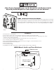
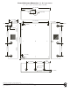
T1MK1F4S and T1MK1F4SD: Configuration of Mercury Boards:
1. Fasten snap on spacers onto metal pems configuration (A), (B), (C) or (D) of backplane depending on the access controller (Fig. 3, pg. 4).
2. Position access controller module over corresponding spacers and depress onto snap on spacers (Fig. 3a, pg. 4).
3. Mount backplane to enclosure with hardware.
Access Controller Position Chart for the Following Models:
Mercury Access Controller Pem Mounting
EP1502, LP1502, MR52, MR16IN, MR16OUT
A
EP1501, LP1501, MR51e, MR62e
B
MR50
C
EP2500, LP2500, MUX8
D
Fig. 3
Snap On
Spacer
Mercury Board
Backplane
Pem
Fig. 3a