
Installation Guide


Trove - 5 -
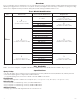
Terminal Identification:
Terminal Legend Function/Description
L, G, N
Connect 115VAC/120VAC 60Hz to these terminals: L to hot, N to neutral, G to ground (non power-limited)
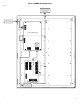
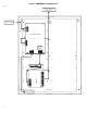
(ULXB - Fig. 3a, pg. 6, eFlow - Fig. 4a, pg. 6).
– DC +
AL300ULXB2 - 12VDC or 24VDC @ 2.5A continuous output (power-limited output) (Fig. 3d, pg. 6).
AL400ULXB2 - 12VDC @ 4A or 24VDC @ 3A continuous output (power-limited output) (Fig. 3d, pg. 6).
AL600ULXB - 12VDC or 24VDC @ 6A continuous output (non power-limited output) (Fig. 3d, pg. 6).
AL1012ULXB - 12VDC @ 10A continuous output (non power-limited output) (Fig. 3d, pg. 6).
AL1024ULXB2 - 24VDC @ 10A continuous output (non power-limited output) (Fig. 3d, pg. 6).
eFlow3NB - 12VDC or 24VDC @ 2A continuous output (power-limited output) (Fig. 4h, pg. 6).
eFlow4NB - 12VDC or 24VDC @ 4A continuous output (power-limited output) (Fig. 4h, pg. 6).
eFlow6NB - 12VDC or 24VDC @ 6A continuous output (non power-limited output) (Fig. 4h, pg. 6).
eFlow102NB - 12VDC @ 10A continuous output (non power-limited output) (Fig. 4h, pg. 6).
eFlow104NB - 24VDC @ 10A continuous output (non power-limited output) (Fig. 4h, pg. 6).
Trigger EOL Supervised
(eFlow only)
Fire Alarm Interface trigger input from a short or FACP. Trigger inputs can be normally open,
normally closed from an FACP output circuit (Power-Limited input) (Fig. 4d, pg. 6).
NO, GND RESET
(eFlow only)
FACP interface latching or non-latching (Power-Limited) (Fig. 4c, pg. 6).
+ AUX –
(eFlow only)
Auxiliary Power-Limited output rated @ 1A (unswitched) (Power-Limited output) (Fig. 4f, pg. 6).
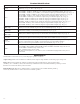
AC Fail
NC, C, NO
Indicates loss of AC power, e.g. connect to audible device or alarm panel. Relay normally energized
when AC power is present. Contact rating 1A @ 30VDC (Power-Limited) (Figs. 3b, 4b, pg. 6).
Bat Fail
NC, C, NO
Indicates low battery condition, e.g. connect to alarm panel. Relay normally energized when DC power
is present. Contact rating 1A @ 30VDC. A removed battery is reported within 5 minutes.
Battery reconnection is reported within 1 minute (Power-Limited) (Figs. 3b, 4b, pg. 6).
– BAT +
Stand-by battery connections (non power-limited) (Figs. 3c, 4g, pg. 6).
AL300ULXB2, AL400ULXB2, AL600ULXB and AL1012ULXB - maximum charge current 0.7A.
AL1024ULXB2 - maximum charge current 3.6A.
eFlow - maximum charge current 1.54A.
Note: Expected battery life is 5 years; however, it is recommended changing batteries in 4 years or
less if needed.
Maintenance:
Unit should be tested at least once a year for the proper operation as follows:
Output Voltage Test: Under normal load conditions, the DC output voltage should be checked for proper voltage level.
Battery Test: Under normal load conditions check that the battery is fully charged, check specified voltage
(12VDC @ 13.2 or 24VDC @ 26.4) both at the battery terminal and at the board terminals marked [– BAT +] to ensure
that there is no break in the battery connection wires.
Replacing Batteries: Disconnect existing batteries. Connect battery to the terminals marked [– BAT +].
Use two (2) 12VDC batteries connected in series for 24VDC operation.