
Installation Manual

Specification Chart:
Installation Instructions:
1. Connect wires to plug-in transformer.
2. Measure output voltage before connecting devices. This helps avoid potential damage.
3. Plug in the transformer to an outlet and secure transformer with screw provided.
WARNING: This installation should be made by qualified service personnel and should conform to
all local codes and in accordance with the National Electrical Codes.
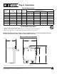
Plug-in Transformer Diagram
Plug-In Transformers
Altronix is not responsible for any typographical errors. Product specifications are subject to change without notice.
140 58th Street, Brooklyn, New York 11220 USA, 718-567-8181, fax: 718-567-9056
website: www.altronix.com, e-mail: info@altronix.com, Made in U.S.A.
IIPlug-In - Rev. 092602 C29K
MEMBER
Model # Output Amp UL Listed
Dimensions (Fig. 1)
A B C D
TP1220 12VAC/20VA 1.7 x 1.8840” 2.5000” 3.0000” 3.3500”
TP1620 16.5VAC/20VA 1.2 x 1.8840” 2.5000” 3.0000” 3.3500”
TP1640 16.5VAC/40VA 2.4 x 2.3530” 2.6580” 3.1860” 3.5620”
TP1650 16.5VAC/50VA 3.0 x 2.3530” 2.6580” 3.1860” 3.5620”
TP2420 24VAC/20VA 0.8 x 1.8840” 2.5000” 3.0000” 3.3500”
TP2440 24VAC/40VA 1.67 x 2.3530” 2.6580” 3.1860” 3.5620”
TP2450 24VAC/50VA 2.0 x 2.3530” 2.6580” 3.1860” 3.5620”
A B
C
D
Fig. 1