
Installation Guide


- 2 - Trove
Overview:
Trove accommodates various combinations of access controllers and accessories from the industry’s leading manufacturers with or without
Altronix power supplies and accessories for access systems. A variety of backplanes offer a wide range of scalable access and power config-
urations. Trove simplifies board layout and wire management, while reducing installation and labor costs.
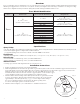
Trove Model Identification:
Series
Trove
Enclosure Size
Backplane Model
(Access Controller Manufacturer)
Backplane Size
Trove
1
18” x 14.5” x 4.625”
(457mm x 368mm x 118mm)
C = CDVI
1
16.625” x 12.5” x 0.06”
(422.3mm x 317.5mm x 1.5mm)
M = Mercury
1
16.625” x 12.5” x 0.3125”
(422.3mm x 317.5mm x 7.9mm)
V = HID/VertX
DM = DMP*
2
27.25” x 21.75” x 6.5”
(692.2mm x 546.1mm x 165.1mm)
AM = AMAG
2
25.375” x 19.375” x 0.3125”
(644.5mm x 492.1mm x 7.94mm)
BH = Bosch*
CV = CDVI
HW = Honeywell*
KA = Keyscan
KH = Kantech*
M = Mercury
SH = Software House
SL = Sielox*
V = HID/VertX
*Not evaluated by UL.
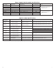
Specifications:
Agency Listings:
• UL 294 - 6th edition. Trove1M and Trove2M Power Controllers: Line Security I, Destructive Attack I, Endurance IV, Stand-by Power II.
• This Class B digital apparatus complies with Canadian ICES-003.
Cet appareil numérique de la classe B est conforme á la norme NMB-003 du Canada.
Environmental:
• Humidity and Temperature conditions as tested by UL (85%, +/-5% @ 30ºC +/-2ºC), ULC (93%, +/-2% @ 32ºC +/-2ºC).
Battery Backup:
• Trove1 enclosure accommodates up to two (2) 12VDC/7AH batteries.
• Trove2 enclosure accommodates up to two (2) 12VDC/12AH batteries.
Additional Features:
• 19 Gauge grey enclosure with ample knockouts for convenient access.
Installation Instructions:
1. Remove backplane from enclosure. Do not discard hardware.
2. Mark and predrill holes in the wall to line up with the top two/three keyholes in the enclosure. Install three upper fasteners and screws
in the wall with the screw heads protruding. Place the enclosure’s upper keyholes over the two/three upper screws, level and secure.
Mark the position of the lower three holes. Remove the enclosure. Drill the lower holes and
install the two/three fasteners. Place the enclosure’s upper keyholes over the two/three upper
screws. Install the two/three lower screws and make sure to tighten all screws.
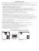
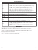
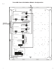
3. Mount included UL Listed tamper switch (Honeywell model 112 or equivalent) in desired
location, opposite hinge. Slide the tamper switch bracket onto the edge of the enclosure
approximately 2” from the right side (Fig. 1, pg. 2). Connect tamper switch wiring to
the Access Control Panel input or the appropriate UL Listed reporting device.
To activate alarm signal open the door of the enclosure.
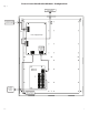
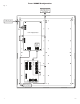
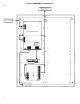
4. Mount boards to backplane, refer to individual Trove installation instructions.
Edge of
Enclosure
to Access Control Panel
or U.L. Listed
Reporting Device
Enclosure
Honeywell
model # 112
Tamper Switch
or equivalent
(provided)
Fig. 1