
Installation Guide

Trove1PD1 / TPD1 - 3 -
TPD1: Configuration of Altronix Power Supply and PDK Modules
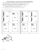
1. Fasten standoffs (provided) to pems that match the hole pattern for Altronix Power Supply/Chargers (Fig. 2, pg. 3).
Fasten metal standoffs in the correct locations to provide proper grounding, see below (Fig. 2, pg. 3).
2. Mount boards to standoffs utilizing 5/16” pan head screws (provided) (Fig. 2a, pg. 3).
3. Fasten standoffs (provided) to pems that match the hole pattern for PDK PM-07-EIOE-E modules.
Mount boards to standoffs utilizing 5/16” pan head screws (provided) (Fig. 2, 2a, pg. 3).
Note: PDK PM-07-EIOE-E modules have one (1) RJ45 jack each.
Please make sure that they are mounted correctly, as shown in Fig. 2 below.
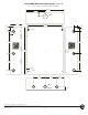
4. Fasten TPD1 backplane to Trove1 enclosure utilizing pan head screws (provided).
Fig. 2 - Trove1PD1/TPD1 Configurations
Metal
Standoff
Placement
Metal
Standoff
Placement
Metal
Standoff
Placement
Altronix
Power
Supply
Altronix
Power
Supply
Altronix
Power
Supply
RJ45 Jack
RJ45 Jack
RJ45 Jack
RJ45 Jack
RJ45 Jack
PDK
PM028P
PDK
PM028P
PDK
PM028P
PDK
PM028P
PDK
PM028P
Pem
Standoff
Altronix
Power Supply or
Sub-Assembly
Backplane
Pan Head
Screw
Fig. 2a