
Installation Instructions


- 6 - VertiLine33DV / 63DV Series Installation Guide
(ON)
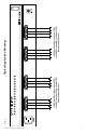
1.625" (41.3mm)
REAR
FRONT
TOP & BOTTOM
8.5" (216mm)
0.75" (19.05mm)
19.125" (486mm)
17.625" (447.7mm)
1U EIA 19” Rack Mount Chassis
Mechanical Drawing & Dimensions (H x W x D):
1.625” x 19.125” x 8.5” (41.3mm x 486mm x 216mm)
Fig. 3
Power Switch With Built-In Circuit Breaker:
OFF position - Switch not illuminated. Outputs not powered.
RESET (ON) position - Switch illuminated. Outputs powered.
Circuit breaker tripped - Switch not illuminated.
Power LEDs on faceplate are not illuminated. Outputs not powered.
To reset circuit breaker set power switch to the ON (RESET) position
(Fig. 3, pg. 6).
The lightning flash with arrowhead symbol within an equilateral triangle is intended to alert the user
to the presence of an insulated DANGEROUS VOLTAGE within the product’s enclosure that may be of
sufficient magnitude to constitute an electric shock.
The exclamation point within an equilateral triangle is intended to alert the user to the presence of impor-
tant operating and maintenance (servicing) instructions in the literature accompanying the appliance.
CAUTION: To reduce the risk of electric shock do not open enclosure.
There are no user serviceable parts inside.
Refer servicing to qualified service personnel.