VertiLine3D Series Rack Mount Power Supplies Models Include: VertiLine3D - 12VDC @ 8A - Eight (8) PTC protected outputs VertiLine6D - 24VDC @ 8A - Eight (8) PTC protected outputs Installation Guide Rev. 090710 More than just power.TM Installing Company: _______________ Service Rep.
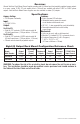
Overview: Altronix VertiLine Rack Mount Power Supplies provide eight (8) filtered and electronically regulated power outputs in a space saving 1U EIA 19” rack mount chassis. The units are available with either 12VDC or 24VDC power outputs. VertiLine Rack Mount Power Supplies are also available in sixteen (16) outputs. Specifications: Agency Listing: Features: • CE European Conformity. • Eight (8) power LED indicators. • Illuminated master power disconnect circuit breaker with manual reset.
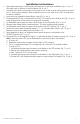
Installation Instructions: 1. Attach mounting brackets to VertiLine unit for desired rack or wall mount installation (Figs. 4-5, pg. 7). Affix rubber pads to VertiLine for shelf installation (Fig. 6, pg. 7). 2. Secure the unit into rack, mount unit to wall or place unit on a shelf as desired (unit should be spaced at least 3” from any video monitors). When installing the unit in a rack, allow for one half U spacing above the unit for ventilation. 3. Insert and secure removable terminal blocks to unit (Fig.
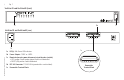
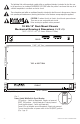
-4- Fig. 1 VertiLine3D and VertiLine6D (front) 1a 1b VertiLine3D and VertiLine6D (rear) 1d VertiLine3D / VertiLine6D Installation Guide 1a LED(s) 1-8: Power LED indicators. 1b Power Outputs: 12VDC or 24VDC. 1c Illuminated master power disconnect circuit breaker (switch): • OFF position Circuit breaker tripped Switch not illuminated. • RESET (ON) position Switch illuminated. 1d IEC 320 Connector: 115VAC 60Hz (grounded line cord included). 1e Removable Terminal Block.
VertiLine3D / VertiLine6D Installation Guide Fig.
The lightning flash with arrowhead symbol within an equilateral triangle is intended to alert the user to the presence of an insulated DANGEROUS VOLTAGE within the product’s enclosure that may be of sufficient magnitude to constitute an electric shock. The exclamation point within an equilateral triangle is intended to alert the user to the presence of important operating and maintenance (servicing) instructions in the literature accompanying the appliance.
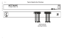
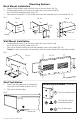
Mounting Options: Rack Mount Installation 1. 2. 3. Remove factory installed screws from both sides of the rack chassis (Fig. 4a). Install mounting brackets (A) on the left and right side of rack chassis using the two (2) flat head screws (B) (included) (Fig. 4b). Place unit into desired EIA 19” rack position and secure with mounting screws (not included) (Fig. 4c). Fig. 4 Fig. 4a Fig. 4b Top Fig.
Notes: Altronix is not responsible for any typographical errors. –––––––––––––––––––––––––––––––––––––––––––––––––––––––––––––––––––––––––––––––––––––––––––––––––––––––––––––––– 140 58th Street, Brooklyn, New York 11220 USA | phone: 718-567-8181 | fax: 718-567-9056 website: www.altronix.com | e-mail: info@altronix.