
Installation Guide

WayPoint10A Series - 3 -
10. WayPoint10A4U/A4DU, WayPoint10A8U/A8DU are factory set for 24VAC operation.
For 28VAC operation adjust unit prior to mounting and applying power as follows:
Change the wire position so that the black wire [28V] is connected to the terminal marked [P] and
the yellow wire [24V] is connected to the terminal marked [S].
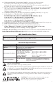
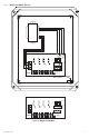
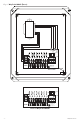
11. Measure output voltage on terminals marked [COM, 24V, 28V] on WayPoint10AU or WayPoint10ADU
(Fig. 2, pg. 4) or [1-4] or [1-8 COM] on WayPoint10A4U, WayPoint10A4DU, WayPoint10A8U and
WayPoint10A8DU before connecting devices (Fig. 3, pg. 5, Fig. 4, pg. 6).
This helps avoiding potential damage.
12. Set illuminated master power disconnect circuit breaker to the [OFF] position (Figs. 2-4, pgs. 4-6).
13. Connecting devices to WayPoint10AU or WayPoint10ADU:
For 24VAC output connect devices to terminals marked [COM, 24V] (Fig. 2, pg. 4).
For 28VAC output connect devices to terminals marked [COM, 28V] (Fig. 2, pg. 4).
Connecting devices to WayPoint10A4U or WayPoint10A4DU:
Connect device to terminals marked [1-4] and [COM] (Fig. 3, pg. 5).
Connecting devices to WayPoint10A8U or WayPoint10A8DU:
Connect device to terminals marked [1-8] and [COM] (Fig. 4, pg. 6).
14. Set illuminated master power disconnect circuit breaker to the [RESET/ON] position (Figs. 2-4, pgs. 4-6).
15. LEDs will illuminate indicating each output is powered (Figs. 2-4, pgs. 4-6).
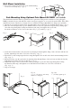
16. Upon completion of wiring secure enclosure door with latches and optional lock.
Caution: Equipment to be installed / serviced by authorized / trained personnel only.
Shut branch circuit power before installing / servicing equipment.
WARNING: When installing in a non-restricted service area use lock or other fastened means on door
latches. This installation should be made by qualified service personnel and should conform to the
National Electrical Code and all local codes.
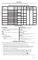
LED Identification Chart:
ON OFF
Normal operating condition.
No AC output. Blown fuse or tripped PTC, illuminated master power disconnect
circuit breaker is tripped or OFF, AC failure.
To reset a tripped PTC turn the power off for 1 minute and then turn it back on.
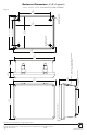
Technical Specifications:
Parameter Description
Input power requirements
115VAC, 60Hz, 1A or 230VAC, 50Hz, 0.5A.
Indicators
Individual power output LED indicators.
Illuminated master power switch.
Environmental Conditions
Operating Ambient Temperature:
For 24VAC @ 4A output: - 40°C to 60°C (- 40°F to 140ºF).
For 28VAC @ 3.5A output: - 40°C to 70°C (- 40°F to 158ºF).
Relative Humidity: 85%, +/- 5%
Storage Temperature: - 40ºC to 75ºC (- 40ºF to 167ºF).
Operating Altitude: - 304.8 to 2,000m.
Regulatory Compliance
UL/cUL Listed for Information Technology Equipment (UL 60950-1)
Equipment to be Installed Outdoors (UL 60950-22).
CE European Conformity.
For fuse protected models:
Replace fuses with the same type and rating 5A/32V.
The lightning flash with arrowhead symbol within an equilateral triangle is intended to alert the user
to the presence of an insulated DANGEROUS VOLTAGE within the product’s enclosure that may
be of sufficient magnitude to constitute an electric shock.
The exclamation point within an equilateral triangle is intended to alert the user to the presence of
important operating and maintenance (servicing) instructions in the literature accompanying the
appliance.
CAUTION: To reduce the risk of electric shock do not open
enclosure. There are no user serviceable parts inside.
Refer servicing to qualified service personnel.
5A
32V