User Manual KM0216 KM0432 2004-08-04
FCC Information This is an FCC Class A product. In a domestic environment this product may cause radio interference in which case the user may be required to take adequate measures. This equipment has been tested and found to comply with the limits for a Class A digital device, pursuant to Part 15 of the FCC Rules. These limits are designed to provide reasonable protection against harmful interference when the equipment is operated in a commercial environment.
Package Contents The complete KM0216 / KM0432 package consists of the following components: w 1 KM0216 or KM0432 Modular Matrix KVM Switch w 1 Power Cord w 1 User Manual w 1 Quick Start Guide w 1 Warranty Registration Card Check to make sure that all of the components are present and in good order. If anything is missing, or was damaged in shipping, contact your dealer.
Contents Chapter 1. Introduction Benefits . . . . . . . . . . . . . . Features . . . . . . . . . . . . . . Hardware Requirements . . . . . . Console . . . . . . . . . . . . Computers . . . . . . . . . . . Cables . . . . . . . . . . . . . KM0216 / KM0432 Front View . KM0216 / KM0432 Rear View . . Console Modules . . . . . . . . . Console Modules Front View Console Modules Rear View . . . . . . . . . . . . . . . . . . . . . . . . . . . . . . . . . . . . . . . . . . . . . . . . . . . . . . . . . . . . .
Chapter 3. OSD Operation OSD Overview . . . . . . . OSD Main Screen Headings . OSD Navigation . . . . . . . OSD Functions . . . . . . . F1 GOTO: . . . . . . . . F2 LIST: . . . . . . . . . F3 SET: . . . . . . . . . F4 ADM: . . . . . . . . F5 SKP: . . . . . . . . . F6 BRC: . . . . . . . . . F7 SCAN: . . . . . . . . F8 LOUT: . . . . . . . . Cascaded OSD Operation . . . . . . . . . . . . . . . . . . . . . . . . . . . . . . . . . . . . . . . . . . . . . . . . . . . . . . . . . . . . . . . . . . . . . . .
Chapter 6. The Firmware Upgrade Utility Introduction . . . . . . . . . Purpose . . . . . . . . . Before You Begin . . . . Performing the Upgrade . . . Starting the Upgrade . . . . . . . . . . . . . . . Upgrade Failed . . . . . Firmware Upgrade Recovery . . . . . . . . . . . . . . . . . . . . . . . . . . . . . . . . . . . . . . . . . . . . . . . . . . . . . . . . . . . . . . . . . . . . . . . . . . . . . . . . . . . . . . . . . . . . . . . . . . . . . . . . . . . . . . . . . . . . . . . . .
About This Manual This User Manual provides information on all aspects of installing, configuring and operating your KM0216 / KM0432 Modular Matrix KVM switch. An overview of the information found in the manual is provided below. Overview Chapter 1, Introduction, introduces you to the KM0216 / KM0432 System. Its purpose, features and benefits are are presented; its front and back panel components are explained; and the modules used to connect to it are described.
Conventions This manual uses the following conventions: Courier Indicates text that you should key in. [] Indicates keys you should press. For example, [Enter] means to press the Enter key. If keys need to be chorded, they appear together in the same bracket with a plus sign between them: [Ctrl+Alt]. 1. Numbered lists represent procedures with sequential steps. w Bullet lists provide information > Indicates selecting an option on a menu.
ALTUSEN Technical Support North America Technical Phone Support Registered ALTUSEN product owners are entitled to telephone technical support. Call the ALTUSEN Technical Support Center: 949-453-8885. International Technical Phone Support 1. Contact your local dealer. 2. Call the ALTUSEN Technical Support Center: (886-2) 8692-6959. Email Support Email your questions and concerns to: support@altusen.com Online Troubleshooting The ALTUSEN support website: http://www.altusen.
Notes: x 2004-08-04
Chapter 1. Introduction The KM0216 / KM0432 Matrix KVM Switch gives IT administrators in large corporations advanced control of multiple servers. Operators working at up to two (KM0216) or four (KM0432) keyboard, mouse, and monitor consoles can simultaneously and independently take direct control of up to 16 (KM0216) or 32 (KM0432) computers. With a combination of daisy chaining and cascading, up to 16 or 32 operators can access and control up to 2,048 or 4,096 computers.
Benefits The KM0216 / KM0432 Matrix KVM switch saves time and money by allowing a single console to manage each of the connected computers. A KM0432 installation provides the following benefits: w Eliminates the cost of a keyboard, monitor, and mouse for each computer. w Eliminates the need for the additional space of the extra components. w Saves on energy costs. w Eliminates the inconvenience, time and effort required to move from one computer to another.
w No software required; convenient computer selection via intuitive hotkey combinations or On Screen Display (OSD) menus w OSD port list automatically expands when stations are added - port names are automatically reconfigured when the station sequence is changed w OSD screen automatically adjusts to resolution changes w Auto Scan feature for monitoring user-selected computers w Three level password security: Super Administrator, Administrator, and Users w LCD, VGA, SVGA, XGA, and MultiSync support; DDC2B w
Hardware Requirements Console The following equipment must be used for each console: w A VGA, SVGA, or Multisync monitor capable of the highest resolution that you will be using on any computer in the installation. w Either a PS/2 or a USB keyboard and mouse. Computers The following equipment must be installed on each computer: w An HDB-15 video port or, for legacy Sun systems, a Sun 13W3 video port.
KM0216 / KM0432 Front View 2-USER, 16-PORT MATRIX KVM MODEL NO. KM0216 1 2 3 4 5 KM0216 4-USER, 32-PORT MATRIX KVM MODEL NO.
1. Firmware Upgrade Recovery Switch During normal operation and while performing a fimware upgrade, this switch should be in the NORMAL position. See p. 61 for firmware upgrade recovery details. After returning the switch to its prior firmware state, slide the switch back to the NORMAL position to attempt the firmware upgrade again, or to use the switch with its prior firmware. 2.
5. Station ID LED The KM0432’s Station ID is displayed here. If this is a Single Station installation (see p. 14), or the First Station on a Daisy Chained installation (see p. 19), the KM0216 / KM0432 has a Station ID of 01. On a Daisy Chained installation, the KM0216 / KM0432 auto-senses its position and displays the Station ID that corresponds to its place in the chain. (see Port ID Numbering, p. 31 for details).
KM0216 / KM0432 Rear View 1 2 3 1 4 2 1 2 3 4 5 6 7 8 5 9 10 11 12 13 14 15 16 6 KM0216 1 2 4 3 3 4 1 2 17 18 19 20 21 22 23 24 25 26 27 28 29 30 31 32 1 2 3 4 5 6 7 8 9 10 11 12 13 14 15 16 5 6 KM0432 8 2004-08-04
1. Power Socket The power cord to the AC source plugs in here. 2. Power Switch This is a standard rocker switch that powers the unit On and Off. 3. Console Port Section The Cat. 5 cables from the Console Modules (see p. 10) plug in here. 4. Firmware Upgrade Port The Firmware Upgrade Cable that transfers the firmware upgrade data from the administrator’s computer to the KM0216 / KM0432 (see p. 62), plugs into this RJ-45 connector. 5. Daisy Chain Ports When Daisy Chaining Units (see p.
Console Modules The purpose of the Console Modules is to provide flexibility for your installation by allowing PS/2 and USB interfaces to be mixed and matched at the console side. At the same time, KVM Adapter cables allow PS/2, USB and Sun interfaces to be mixed and matched at the computer side. With this approach, either type of console can access and control any type of computer.
Console Modules Rear View 1 2 4 3 KA9220 1 2 4 3 KA9270 1. Power Jack The power adapter cable plugs in here. 2. I/O Jack The cable that links the module to the KM0216 / KM0432 plugs in here. 3. Firmware Upgrade Recovery Switch During normal operation and while performing a fimware upgrade, this switch should be in the NORMAL position. See p. 6 for details about this switch. 4. Console Port Section The cables from your keyboard, monitor and mouse plug in here.
Notes: 12 2004-08-04
Chapter 2. Installation Overview For convenience and flexibility that allows mixing the PS/2 and USB interfaces, the KM0216 / KM0432’s design utilizes Console Modules that act as signal translation intermediaries between the consoles and the switch, and KVM Adapter Cables, that serve as intermediaries between the switch and the computers: KA9131 KA9120 KM0432 KA9220 or KA9270 KA9170 KA9130 A separate console module is required for each console you connect.
Before you Begin 1. Make sure that power to all the devices you will be connecting up have been turned off. You must unplug the power cords of any computers that have the Keyboard Power On function. 2. To prevent damage to your installation, make sure that all devices on the installation are properly grounded. Single Stage Installation In a Single Stage installation, there are no additional KVM switches daisy chained or cascaded down from the first unit.
3. Connect the KM0216 / KM0432 to the KVM Adapter Cable Use Cat. 5 cable to connect any available CPU Port to a KVM adapter cable that is appropriate for the computer you are installing (see the table on p. 4 for details). Note: The distance between the KM0216 / KM0432 and the KVM Adapter Cable must not exceed 150m (500’). 4. Connect the KVM Adapter Cable to the Computer. Plug the connectors on the KVM cable into the appropriate ports of the computer you are installing.
1 KA9220 4 2 6 3 3 4 1 2 17 18 19 20 21 22 23 24 25 26 27 28 29 30 31 32 1 2 3 4 5 6 7 8 9 10 11 12 13 14 15 16 5 KA9270 EN AT by S E L U 20 D 1 O 9 M KA U .
USB Cable Connection: 4 PS/2 Cable Connection: 4 17 2004-08-04
Multilevel Installations The number of computers that can be added to your installation can be greatly expanded by performing a multilevel installation. The KM0216 / KM0432 supports three types of multilevel installation: w Daisy chained w Cascaded w Daisy chained plus cascaded Overview Daisy chaining refers to connecting two KVM switches via dedicated daisy chain ports. The switches are strung together in a chain (see the diagram on p.
Daisy Chaining Up to 7 additional KM0216 / KM0432 units can be daisy chained together; each capable of supporting four independent consoles. The first KM0216 / KM0432 is considered the Master unit; the daisy chained KM0216 / KM0432s are considered Slaves. In a complete daisy chained installation, the two (KM0216) or four (KM0432) consoles that belong to the Master switch can access and control all of the computers (up to 128 or 256) on the installation.
7. Power up the installation according to the following procedure: a. Switch on the power for the First Station. Wait for the unit to ascertain its Station ID and display it on the Station ID LED. (The Station ID for the First Stage unit is 01, the ID for the Second Stage unit is 02, the ID for the Third Stage unit is 03, etc.). b. Switch on the power for each Station on the installation in turn (Second Station, then Third Station, etc.).
Cascading Another way of adding capacity is to cascade additional KVM switches from the KM0216 / KM0432’s CPU ports. Up to 16 (KM0216) or 32 (KM0432) additional switches can be cascaded. Unlike daisy chaining, however, cascading does not increase the number of consoles that can be used to control the computers. Note: 1. While you can daisy chain KM0216 / KM0432s, you cannot cascade them. 2. Switches cannot be cascaded beyond the second stage.
3. Use KVM cable sets (as described in the Cables section of the Second Stage unit’s User Manual), to connect any available CPU port on the Second Stage unit to the Keyboard, Video, and Mouse ports of the computer you are installing. 4. Plug the Second Stage unit’s power cord into the unit’s Power Socket; then plug it into an AC source. 5. Repeat steps 2 - 4 for any other Second Stage units you wish to connect. 6.
Physical Interface Cascading: Physical Interface Cascading refers to cascading to a second stage KVM switch (such as the Altusen KH0116) that doesn’t utilize the same protocol as the first stage KM0216 / KM0432, but uses the same physical interface (PS/2 or USB ports, for example). The advantage of cascading to a switch like the KH0116 is that it yields enormous expansion capability.
To set up a Physical Interface Cascade, refer to the installation diagram on p. 25, and do the following: 1. Make sure that power to all the devices you will be connecting up has been turned off. 2. Use Cat 5 cable to connect any available CPU Port on the First Stage unit (the KM0216 / KM0432) to a PS/2 style KVM adapter cable (as described in the Cables section, p. 4); plug the adapter cable’s KVM connectors to the Keyboard, Video, and Mouse Console ports of the KH0116.
3 4 1 2 17 18 19 20 21 22 23 24 25 26 27 28 29 30 31 32 1 2 3 4 5 6 7 8 9 10 11 12 13 14 15 16 KA9120 KH0116 KH0116 25 2004-08-04
Daisy Chaining Plus Cascading Expansion KM0216 / KM0432 units can be daisy chained to other KM0216 / KM0432 units to produce extremely large KVM matrixes. Under Protocol Interface Expansion, up to 8 daisy chained 16 or 32 port KM0216s / KM0432s can have 8 KH88s cascaded from each port, allowing up to 1,024 or 2,048 computers and 32 consoles in a full installation (8 x 16 x 8 or 8 x 32 x 8).
3 4 1 2 17 18 19 20 21 22 23 24 25 26 27 28 29 30 31 32 1 2 3 4 5 6 7 8 9 10 11 12 13 14 15 16 17 18 19 20 21 22 23 24 25 26 27 28 29 30 31 32 1 2 3 4 5 6 7 8 9 10 11 12 13 14 15 16 KA9120 3 4 1 2 KA9120 27 2004-08-04
Physical Interface Expansion To set up a daisy chained/cascaded installation under Physical Interface Expansion, refer to the diagram below, and do the following: 1. Follow the cabling up procedures given in the Daisy Chaining sections. 2. Power up the daisy chained KM0216 / KM0432 Stations according to the sequence given in the Daisy Chaining section (p. 20). 3.
Topology Considerations The use of RJ-45 CPU connectors, combined with Auto Signal Compensation (ASC), allow signals to travel up to 500 feet (150 meters) and still maintain reliability and high video resolution. This allows the KM0216 / KM0432 installation to take advantage of the internal CAT 5e and CAT6 wiring built in to most modern commercial buildings. Note: Although the KM0216 / KM0432 supports legacy CAT5 wiring, the performance and video quality may degrade over longer distances.
Powering Off and Restarting Powering off the KM0216 / KM0432 does not affect the computers attached to it. When you restart the KM0216 / KM0432, you will regain control immediately. To replace a KM0216 / KM0432, simply power it down; unplug the cables; plug them into the new unit; and power the new unit on. Note: If any of the computers behave strangely after powering off and restarting, or changing a switch, simply restart the computer.
Port ID Numbering Each CPU port on a KM0216 / KM0432 installation is assigned a unique Port ID. You can access and control any computer on the installation by specifying the Port ID of the port that it is connected to. Depending on where the computer is on the installation, its Port ID will have either two or three parts.
Cascaded Physical Interface Installations: Under Physical Interface Expansion, KH0116s are cascaded down from the KM0216 / KM0432. Since the OSD protocols are different, there are separate OSDs for each. When you invoke the OSD (see p. 35), the KM0216 / KM0432 OSD screen comes up first. When you select the port that the target KH0116 is connected to, its OSD screen replaces the KM0216 / KM0432’s, and you can select the computer you want to access from the KH0116 OSD screen.
The Administrator’s power is limited to only that segment of the installation that the KM0216 / KM0432 he is logged in on controls. He can assign and change passwords and access rights for all operators on his segment. Both Super Administrator and Administrator have full User rights. The four Users have no administrative rights.
Notes: 34 2004-08-04
Chapter 3. OSD Operation OSD Overview The KM0216 / KM0432 On Screen Display (OSD) provides a visual, menu-driven, mouse enabled, interface that offers quick and convenient computer access and control, as well as efficient system administration including user management (access rights, passwords, etc.). Each OSD menu option activates a function that configures and controls the operation of the KVM installation. All procedures start from the OSD Main Screen.
After you log in, a screen similar to the one below appears: F 1 : G OT O F 3 : S ET F5:SKP F 2 : L I ST F4:ADM F6:BRC S U P E R A D M I N I ST R AT O R LIST:ALL PN QV NAME 01 02 03 06 05 06 07 08 3 4 5 F7:SCAN X z F 8 : L O U T zz SN:02/08 ATEN INTL.CO. 1 ATEN INTL.CO. 2 ATEN INTL.CO. 3 FAX SERVER 1 FAX SERVER 2 WEB SERVER 1 WEB SERVER 2 MAIL SERVER 1 Note: 1. The diagram depicts the Super Administrator’s Main Screen.
OSD Main Screen Headings Heading Explanation SN This field shows the Station Number that the currently selected port is connected to. The first number is the Station’s position in the chain; the second number shows the total number of stations in the chain. PN This column lists the Port Numbers for all the CPU ports on the installation. The simplest method to access a particular computer is move the Highlight Bar to it, then press Enter.
OSD Functions OSD functions configure and control the OSD. Examples of what can be accomplished with the OSD include: rapidly switching to any port; auto scanning specifically selected ports; limiting the list of ports you wish to view; designating a port as a Quick View Port; managing port names; user management, system administration, and making OSD setting adjustments. To access an OSD function: 1. Either Click a Function Key field at the top of the Main Screen, or press a Function Key on the keyboard.
F2 LIST: Many of the OSD functions only operate on the computers that are currently displayed (listed) on the Main Screen. This function lets you broaden or narrow the scope of which ports the OSD lists on the Main Screen. The submenu choices and their meanings are given in the table below: Choice Meaning ALL Lists all of the ports on the installation. POWERED ON Lists only the ports that have their attached computers Powered On.
F3 SET: This function allows each operator to set up his own working environment. A separate profile for each is stored by the OSD and is activated according to the Username that is provided during Login. To change a setting: 1. Double Click it; or move the highlight bar to it, then press [Enter]. 2. After you select an item, a submenu with further choices appears. To make a selection, either Double Click it; or move the Highlight Bar to it, then press [Enter].
(F3 SET: continued) Setting Function PORT ID DISPLAY DURATION Determines how long a Port ID displays on the monitor after a port change has taken place. The choices are: User Defined - which lets you select the amount of time (from 1 - 255 sec.); and Always On - which displays the Port ID at all times. If you select User Defined, key in the number of seconds, then press [Enter]. The default is 3 Seconds. A setting of 0 (zero) disables this function.
F4 ADM: F4 is a Super Administrator and Administrator only function. It allows them to configure and control the overall operation of the OSD. To change a setting Double Click it; or use the Up and Down Arrow Keys to move the highlight bar to it then press [Enter]. After you select an item, a submenu with further choices appears. Double Click the choice you want, or move the Highlight Bar to it then press [Enter]. An icon appears before the selected choice to indicate which one it is.
(F4 ADM: continued) Setting EDIT PORT NAMES Function To help remember which computer is attached to a particular port, every port can be given a name. This function allows the Administrator to create, modify, or delete port names. To Edit a port name: 1. Click the port you want, or use the Navigation Keys to move the highlight bar to it, then press [Enter]. 2. Key in the new Port Name, or modify/delete the old one. The maximum number of characters allowed for the Port Name is 15.
(F4 ADM: continued) Setting SET QUICK VIEW PORTS Function This function lets the Administrator select which Ports to include as Quick View ports. w To select/deselect a port as a Quick View Port, Double Click the port you want, or use the Navigation Keys to move the highlight bar to it, then press [Enter]. w When a port has been selected as a Quick View Port, an arrowhead displays in the QV column of the LIST on the Main Screen to indicate so. When a port is deselected, the arrowhead disappears.
(F4 ADM: continued) Setting Function SET KEYBOARD LANGUAGE This function allows the Administrator to define the keyboard language layout for each port. To assign a keyboard language, select the target port; then press the [Spacebar] to cycle through the choices: US English; Japanese; or French. The default is US English. SET OPERATING PLATFORM This function allows the Administrator to define the operating platform for the computer connected to each port.
F5 SKP: This function enables you to easily skip backward or forward - switching the console focus from the currently active computer port to the previous or next available one. w The selection of computers to be available for Skip Mode switching is made with the Scan/Skip Mode setting under the F3 SET function (see p. 41).
F6 BRC: F6 is a Super Administrator or Administrator only function. Clicking the F6 field, or pressing [F6], invokes Broadcast (BRC) Mode. When this function is in effect, commands sent from the console are broadcast to to all available computers on the installation. This function is particularly useful for operations that need to be performed on multiple computers, such as performing a system wide shutdown, installing or upgrading software, etc. BRC works in conjunction with the F2 LIST function.
F7 SCAN: This function allows you to automatically switch among the available computers at regular intervals so that you can monitor their activity without having to take the trouble of switching yourself. w The selection of computers to be included for Auto Scanning is made with the Scan/Skip Mode setting under the F3 SET function (see p. 41). w The amount of time that each Port displays for is set with the Scan Duration setting under the F3 SET function (see p. 41).
F8 LOUT: LOUT (Log Out) logs you out of OSD control of the computers, and blanks the Console screen. This is different from simply pressing [Esc] to deactivate the OSD when you are at the Main Screen. With this function you must log in all over again to regain access to the OSD, whereas with [Esc], all you have to do to reenter the OSD is tap the OSD Hotkey. Note: 1. When you reenter the OSD after logging out, the screen stays blank except for the OSD Main Screen.
Cascaded OSD Operation Under Protocol Interface Cascading (see p. 21), the OSDs of the cascaded switches are all seamlessly integrated into the KM0216 / KM0432’s OSD so that all ports can be accessed from there. Under Physical Interface Cascading (see p. 23), however, there are two separate OSDs: one for the KM0216 / KM0432, and one for the cascaded switch.
Chapter 4. Hotkey Operation Hotkey Port Control Hotkey Port Control allows you to provide KVM focus to a particular computer directly from the keyboard. Note: Hotkeys work best in single stage and basic cascaded or daisy chained installations. For complicated daisy chain+cascaded installations, it is simpler, more convenient, and more efficient to use the OSD.
When HKM is active: w The Caps Lock, and Scroll Lock LEDs flash in succession to indicate so. They stop flashing and revert to normal status when you exit HKM. w A Command Line appears at the bottom of the monitor screen. The command line prompt is the word Hotkey: in white text on a blue background. Text that you key in while in HKM displays here. w Ordinary keyboard and mouse functions are suspended - only Hotkey compliant keystrokes and mouse clicks (described in the sections that follow), can be input.
Auto Scanning Auto Scan switches among all the CPU Ports that are accessible to the current Operator at regular intervals (see Scan/Skip Mode, p. 41, for information regarding accessible ports). This function is convenient for automatically monitoring the activity of the computers on the installation. Setting the Scan Interval: The amount of time Auto Scan dwells on each port is set with the Scan Duration setting of the OSD F3 SET function (see p. 41).
Invoking Auto Scan: To start Auto Scanning, key in the following Hotkey combination: 1. Invoke HKM (see p. 51). 2. Press [A]. After you press A, you automatically exit HKM, and enter Auto Scan Mode, and Auto Scanning begins. w While you are in Auto Scan Mode, you can pause the scanning in order to keep the focus on a particular computer either by pressing P or with a Left Click of the mouse. During the time that Auto Scanning is paused, the Command Line displays: Auto Scan: Paused.
Skip Mode This feature allows you to switch between computers in order to monitor them manually. In contrast to Auto Scanning, which automatically switches after a fixed interval, Skip Mode lets you dwell on a particular port for as long or as little as you like. To invoke Skip Mode, key in the following Hotkey combination: 1. Invoke HKM (see p. 51). 2. Key in [Arrow] w Where [Arrow] refers to one of the Arrow keys.
Hotkey Beeper Control The Beeper (see Activate Beeper, p. 43) can be Hotkey toggled On and Off. To toggle the Beeper, key in the following Hotkey combination: 1. Invoke HKM (see p. 51). 2. Press [B] After you press B, the Beeper toggles On or Off. The Command Line displays Beeper On or Beeper Off for one second; then the message disappears and you automatically exit HKM. Hotkey Summary Table [Num Lock] + [ * ] or [Port ID] [Enter] Switches access to the computer that corresponds to that Port ID.
Chapter 5. Multiplatform Support The KM0216 / KM0432 provides the utmost in flexibility for your installation by offering multiplatform support. Through the use of Console Modules and KVM Adapter Cables, PS/2 and USB interfaces can be mixed and matched at the console side, and PS/2, USB and Sun interfaces can be mixed and matched at the computer side. With this approach, either type of console can access and control multiple computer types - PC compatible, Sun and Mac. (See pp.
Sun Keyboard Emulation PC Keyboard Sun Keyboard [Ctrl] [T] Stop [Ctrl] [F2] Again [Ctrl] [F3] Props [Ctrl] [F4] Undo [Ctrl] [F5] Front [Ctrl] [F6] Copy [Ctrl] [F7] Open [Ctrl] [F8] Paste [Ctrl] [F9] Find [Ctrl] [F10] Cut [Ctrl] [1] [Ctrl] [2] - [Ctrl] [3] + [Ctrl] [4] [Ctrl] [H] Help App Compose Win Key u Note: When using [Ctrl] combinatons, press and release the Ctrl key, then press and release the activation key.
Mac Keyboard Emulation PC Keyboard Mac Keyboard [Shift] Shift [Ctrl] Ctrl [Win] [Ctrl] [1] Mult [Ctrl] [2] V_DN [Ctrl] [3] V_UP [Ctrl] [4] [Alt] L Alt/Option [Prt_Sc] F13 [Scroll Lock] F14 [Desktop Menu] = [Enter] Return [Back Space] Delete [Ins] Help [Ctrl] [Desktop Menu] F15 Note: When using key combinatons, press and release the first key (Ctrl or Alt), then press and release the activation key.
Notes: 60 2004-08-04
Chapter 6. The Firmware Upgrade Utility Introduction Purpose The purpose of the Windows-based Firmware Upgrade Utility (FWUpgrade.exe) is to provide an automated process for make upgrading the KVM switch’s firmware as smooth and painless as possible. The program comes as part of a Firmware Upgrade Package that is specific for each device. As new firmware revisions become available, new firmware upgrade packages are posted on our web site: http://www.altusen.
Before You Begin To prepare for the firmware upgrade, do the following: 1. From a computer that is not part of your KVM installation go to our Internet support site and choose the model name that relates to your device to get a list of available Firmware Upgrade Packages. 2. Choose the Firmware Upgrade Package you want to install (usually the most recent), and download it to your computer. 3.
Performing the Upgrade Starting the Upgrade To upgrade your firmware: 1. Run the downloaded Firmware Upgrade Package file - either by double clicking the file icon, or by opening a command line and keying in the full path to it. The Firmware Upgrade Utility Welcome screen appears: 2. Read and Agree to the License Agreement (enable the I Agree radio button).
3. Click Next to continue. The Firmware Upgrade Utility main screen appears: The Utility inspects your installation. The devices capable of being upgraded by the package are listed in the Device List panel. Note: 1. Although only one device type is shown in the list (KA9220, for example), all units of that type receive the upgraded. 2. KM0432U and KM0432N refer to two different upgradable ICs on the chained KM0432 devices. 3.
4. When the list is complete, click Next to start the upgrade. w If you enabled Check Firmware Upgrade, the Utility compares the device’s firmware level with that of the upgrade files. If it finds that the device’s version is higher, it brings up a dialog box informing you of the situation and gives you the option to Continue or Cancel. w If you didn’t enable Check Firmware Upgrade, the Utility installs the upgrade files without checking their version level.
w As each device update completes, its status is reported in the Status Messages panel. w When a device group upgrade is successful, the background behind the device group name changes to pink to indicate so; if a member of a device group fails to upgrade successfully, the background behind the device group name changes to red to indicate that there was an upgrade failure in the group. Check the Status Messages to ascertain which device failed to upgrade. 5.
Firmware Upgrade Recovery If the firmware upgrade procedure is unnaturally aborted (due to a power outage, for example), the switch that was being upgraded at the time may become inoperable, and may be incapable of accepting a normal firmware upgrade. If this occurs, to recover, do the following: 1. Slide the unit’s Firmware Upgrade Recovery Switch (see p. 6), to the RECOVER position. 2. Perform a warm reset (see p. 6). The switch is now ready to be upgraded. 3.
Notes: 68 2004-08-04
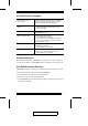
Appendix Connection Tables The following tables indicate the relationship between the number of KVM units and the number of computers that they control: KM0216 Daisy Chain KM0216s Computers 1 1 - 16 2 17 - 32 3 33 - 48 4 49 -64 5 65 - 80 6 81 - 96 7 97- 112 8 113 - 128 KM0216 Cascade to KH88 KVMs Computers KVMs Computers 1 16 - 23 9 72 - 79 2 23 - 30 10 79 - 86 3 30 -37 11 86 - 93 4 37 - 44 12 93 - 100 5 44 - 51 13 100 - 107 6 51- 58 14 107 - 114 7 58 - 65 15
KM0432 Daisy Chain KM0432s Computers 1 1 - 32 2 33 - 64 3 65 - 96 4 97 -128 5 129 - 160 6 161 - 192 7 193- 224 8 225 - 256 KM0432 Cascade to KH88 KVMs Computers KVMs Computers KVMs Computers 1 32 - 39 9 88 - 95 17 144 - 151 25 200 - 207 2 39 - 46 10 95 - 102 18 151 - 158 26 207 - 214 3 46 - 53 11 102 - 109 19 158 - 165 27 214 - 221 4 53 - 60 12 109 - 116 20 165 - 172 28 221 - 228 5 60 - 67 13 116 - 123 21 172 - 179 29 228 - 235 6 67- 74 14 1
OSD Factory Default Settings The factory default settings are as follows: Setting Default OSD Hotkey [Scroll Lock] [Scroll Lock] Port ID Display Position Upper Left Corner Port ID Display Duration 3 Seconds Port ID Display Mode The Port Number plus the Port Name Scan Duration 5 Seconds Scan/Skip Mode All Screen Blanker 0 (Disabled) Hotkey Command Mode Enabled Logout Timeout 0 (Disabled) Beeper Y (Activated) Quick View Ports No ports selected Accessible Ports F (Full) For all Users o
Clear Login Information If you are unable to perform an Administrator login (because the Username and Password information has become corrupted, or you have forgotten it, for example), you can clear the login information with the following procedure: 1. Power off the switch and remove the top cover of the Switch module case. 2. Short the jumper labeled Default Password at the right front of the switch’s main board. 3. Power on the switch.
Specifications Console Modules Function Connectors LEDs KA9220 KA9270 Console KB 1 x mini-DIN-6 F 1 x USB Type A Console Mouse 1 x mini-DIN-6 F 1 x USB Type A Console Monitor 1 x HDB-15 F Link to KM0432 1 x RJ-45 F Power 1 x DC 5V On Line 1 (Amber) Link 1 (Green) 1 x Slide (FW Upgrade Recovery) Switches KVM Adapter Cables Function Connector Plugs KB 1 x mini-DIN-6 M Mouse 1 x mini-DIN-6 M Monitor Link LEDs Switches KA9120 KA9131 / KA9170 1 x USB Type A 1 x HDB-15 M KA9130 1 x
KM0216 / KM0432 Function Computer Connections KM0216 KM0432 Direct 16 32 Max 128 (via 8 level daisy chain) 128 (via 8 level daisy chain) 1024 (via 8 level daisy chain + 2 level cascade) 256 (via 8 level daisy chain) 256 (via 2 level cascade) 2048 (via 8 level daisy chain + 2 level cascade) Console Connections 2 Direct; 16 Max. (via 8 level daisy chain) 4 Direct; 32 Max.
Troubleshooting Symptom Possible Cause Action Operator can only access one port on a cascaded KVM. Cannot switch to any of the other ports. The cascaded KVM’s display channel is being occupied by a previous user. There is only one display channel for all the ports on a cascaded KVM switch. The previous opeator’s access timout expired (see p. 44), so the port is released, but his logout timeout has not expired so the display channel has not been released.
Limited Warranty IN NO EVENT SHALL THE DIRECT VENDOR’S LIABILITY EXCEED THE PRICE PAID FOR THE PRODUCT FROM THE DIRECT, INDIRECT, SPECIAL, INCIDENTAL OR CONSEQUENTIAL DAMAGES RESULTING FROM THE USE OF THE PRODUCT, DISK OR ITS DOCUMENTATION. The direct vendor makes no warranty or representation, expressed, implied, or statutory with respect to the contents or use of this documentation, and specially disclaims its quality, performance, merchantability, or fitness for any particular purpose.
Index A Activate Beeper . . . . . . . . . . . . . . . 43 ADM . . . . . . . . . . . . . . . . . . . . . . . . 42 Administrator functions . . . . . . . . . 42 Advanced Firmware Upgrade . . . . 66 Auto Scanning . . . . . . . . . . . . . 48, 53 Invoking Auto Scan . . . . . . . . . . 54 Pausing Auto Scan . . . . . . . . . . . 54 Scan Duration. . . . . . . . . . . . . . . 41 Setting the Scan Interval . . . . . . 53 Stopping . . . . . . . . . . . . . . . . . . . 54 B Basic Operations. . . . . . . . . . . . . . .
K Keyboard Emulation Mac . . . . . . . . . . . . . . . . . . . . . . 59 Sun . . . . . . . . . . . . . . . . . . . . . . . 58 KM0216 Front View . . . . . . . . . . . . . . . . . . 5 Rear View . . . . . . . . . . . . . . . . . . 8 KM0432 Computer Connection Table 69, 70 Front View . . . . . . . . . . . . . . . . . . 5 Rear View . . . . . . . . . . . . . . . . . . 8 L Port ID Display Duration . . . . . . . . . . . . Display Mode . . . . . . . . . . . . . . Display Position. . . . . . . . . . . . .