
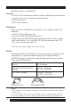
Specifications


18
When the remote console is in control, you can only view through the local
console. When the local console is in control, you can only view through the
remote console.
• The LED indicates which console is currently in use, remote or local.
NOTE: For more information on using KH0116 with a remote console, see Chapter 6.
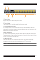
4. Firmware Upgrade Section
The Firmware Upgrade section includes two components (as described below):
Firmware Upgrade Port and Firmware Upgrade Reset Switch.
• The Firmware Upgrade Cable plugs into the Firmware Upgrade Port’s RJ-
11 connector and transfers firmware upgrade data from the administrator’s
computer to the KH0116 (see page 47).
• The Firmware Upgrade Reset Switch is in NORMAL position during normal
operation or while performing a firmware upgrade. If the firmware upgrade
operation does not successfully complete, slide the switch to the RECOVER
position; power Off and restart the switch; slide the switch bakc to the
NORMAL position; power Off and start the switch.
5. Power LED
The Power LED lights when the KH0116 powers up and is ready to operate.
6. Station ID LED
The Station ID LED displays a KH0116’s Station ID and indicates the position of
the particular KVM on the chain when it is part of the daisy chain operation. For a
Single Station or First Station on a Daisy Chain installation the KH0116 Station ID
is 01. On a Daisy Chained installation, the KH0116 auto-senses its position and
displays the Station ID that corresponds to its position in the chain (see Port ID
Numbering, page 25 for details).
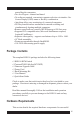
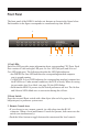
Rear Panel
The rear panel of the KH0116 includes five features as shown in the figure below.
Each number in the figure corresponds to a numbered step that follows.