6 Port High Density KVM Switch KH0116 User Manual www.altusen.
KH0116 User Manual FCC Information This is an FCC Class A product. In a domestic environment this product may cause radio interference in which case the user may be required to take adequate measures. This equipment has been tested and found to comply with the limits for a Class A digital device, pursuant to Part 15 of the FCC Rules. These limits are designed to provide reasonable protection against harmful interference when the equipment is operated in a commercial environment.
KH0116 User Manual User Notice All information, documentation, and specifications contained in this manual are subject to change without prior notification by the manufacturer. The manufacturer makes no representations or warranties, either expressed or implied, with respect to the contents hereof and specifically disclaims any warranties as to merchantability or fitness for any particular purpose. Any of the manufacturer's software described in this manual is sold or licensed `as is'.
KH0116 User Manual Safety Instructions General Read all of these instructions. Save them for future reference. Follow all warnings and instructions marked on the device. Do not place the device on any unstable surface (cart, stand, table, etc.). If the device falls, serious damage will result. Do not use the device near water. Do not place the device near, or over, radiators or heat registers. The device cabinet is provided with slots and openings to allow for adequate ventilation.
KH0116 User Manual Position system cables and power cables carefully; Be sure that nothing rests on any cables. When connecting or disconnecting power to hot pluggable power supplies, observe the following guidelines: Install the power supply before connecting the power cable to the power supply. Unplug the power cable before removing the power supply. If the system has multiple sources of power, disconnect power from the system by unplugging all power cables from the power supplies.
KH0116 User Manual Rack Mounting Before working on the rack, make sure that the stabilizers are secured to the rack, extended to the floor, and that the full weight of the rack rests on the floor. Install front and side stabilizers on a single rack or front stabilizers for joined multiple racks before working on the rack. Always load the rack from the bottom up, and load the heaviest item in the rack first. Make sure that the rack is level and stable before extending a device from the rack.
KH0116 User Manual Package Contents The KH0116 package consists of: 1 KH0116 KVM Switch 2 KVM Cable Sets 1 Firmware Upgrade Cable 1 Power Cord 1 Rack Mount Kit 1 User Manual* 1 Quick Start Guide 1 Registration Card Check to make sure that all of the components are present and in good order. If anything is missing, or was damaged in shipping, contact your dealer.
KH0116 User Manual This Page Intentionally Left Blank viii
KH0116 User Manual Contents FCC Information . . . . . . . . . . . . . . . . . . . . . . . . . . . . . . . . . . . . . . . . . . . . . ii RoHS. . . . . . . . . . . . . . . . . . . . . . . . . . . . . . . . . . . . . . . . . . . . . . . . . . . . . . ii User Notice . . . . . . . . . . . . . . . . . . . . . . . . . . . . . . . . . . . . . . . . . . . . . . . . .iii Safety Instructions. . . . . . . . . . . . . . . . . . . . . . . . . . . . . . . . . . . . . . . . . . . iv General . . . . . . . . . . . . . . .
KH0116 User Manual Chapter 3. OSD Operation Overview. . . . . . . . . . . . . . . . . . . . . . . . . . . . . . . . . . . . . . . . . . . . . . . . . . 19 OSD Navigation . . . . . . . . . . . . . . . . . . . . . . . . . . . . . . . . . . . . . . . . . . . . 21 OSD Main Screen Headings. . . . . . . . . . . . . . . . . . . . . . . . . . . . . . . . . . . 21 OSD Functions . . . . . . . . . . . . . . . . . . . . . . . . . . . . . . . . . . . . . . . . . . . . . 22 F1 GOTO: . . . . . . . . . . . . . . . . . . .
KH0116 User Manual About This Manual This User Manual is provided to help you get the most from your KH0116 system. It covers all aspects of installation, configuration and operation. An overview of the information found in the manual is provided below. Overview Chapter 1, Introduction, introduces you to the KH0116 System. Its purpose, features and benefits are presented, and its front and back panel components are described.
KH0116 User Manual Conventions This manual uses the following conventions: Monospaced Indicates text that you should key in. [] Indicates keys you should press. For example, [Enter] means to press the Enter key. If keys need to be chorded, they appear together in the same bracket with a plus sign between them: [Ctrl+Alt]. 1. Numbered lists represent procedures with sequential steps. ♦ Bullet lists provide information, but do not involve sequential steps.
KH0116 User Manual ALTUSEN Information Technical Support North America Technical Phone Support Registered ALTUSEN product owners are entitled to telephone technical support. Call the ALTUSEN Technical Support Center: 949-453-8885. International Technical Phone Support 1. Contact your local dealer. Email Support Email your questions and concerns to: support@altusen.
KH0116 User Manual Product Information For information about all of ALTUSEN's products and how they can help you connect without limits, visit ALTUSEN on the web or contact an ALTUSEN Authorized Reseller. In the United States of America, call: 866-ALTUSEN (258-8736) In Canada and South America, call: 949-453-8885 In all other locations, call: 886-2-8692-6789 Visit ALTUSEN on the web at http://www.altusen.
Chapter 1 Introduction Overview The KH0116 KVM Switch is a control units that allow access to multiple computers from a single KVM (keyboard, monitor, and mouse) console. Before the development of sophisticated KVM switches, the only way to control large-scale multiple computer configurations from a single console was through a complex and costly network system. Now, with the KH0116, you can easily access multiple computers in a cost effective manner. A single KH0116 can control up to 16 computers.
KH0116 User Manual Access to any computer on the installation is easily accomplished either by entering Hotkey combinations from the keyboard, or by means of a powerful menu driven OSD (On Screen Display) system. A convenient Auto Scan feature also permits automatic scanning and one-by-one monitoring of the activities of selected computers on the installation. There is no better way to save time and money than with a KH0116 installation.
Chapter 1.
KH0116 User Manual Hardware Requirements Console A VGA, SVGA, or Multisync monitor capable of the highest resolution that you will be using on any computer in the installation. A PS/2 style mouse A PS/2 style keyboard Computers The following equipment must be installed on each computer: A VGA, SVGA or Multisync card. A 6-pin mini-DIN (PS/2 style) mouse port. A 6-pin mini-DIN (PS/2 Style) keyboard port. Cables Substandard cables may damage the connected devices or degrade overall performance.
Chapter 1. Introduction Components KH0116 Front View 1 2 No. 1 Component Port LEDs 3 4 5 6 Description The Port LEDs provide status information about their corresponding Computer Ports. There is one pair of LEDs for each Port. The one on the left is the On Line LED; the one on the right is the Selected Port LED: An On Line LED lights ORANGE to indicate that the computer attached to its corresponding port is up and running.
KH0116 User Manual (Continued from previous page.) No. Component Description 3 Remote Console Area The KH0116 can be operated from a remote console (up to 150m away) with the purchase of the CE-250 KVM Extender system. If you choose to use a remote console, its cable plugs into this connector. Normally, both consoles can access the KH0116. Clicking the Disable Remote button to the In position disables the Remote Console – only the Local Console has access to the switch.
Chapter 1. Introduction KH0116 Rear View 1 2 3 4 5 No. Component Description 1 Power Socket 2 Power Switch 3 Local Console If this is a Single Station installation, or if this is the First Port Section Station of a daisy chained installation, the keyboard, monitor, and mouse that make up the Local Console plug in here. 4 Daisy Chain Ports When Daisy Chaining Units (see p. 11), the daisy chain cables plug in here.* The upper port is the Chain In port; the lower one is the Chain Out port.
KH0116 User Manual This Page Intentionally Left Blank 8
Chapter 2 Installation and Operation Before You Begin 1. Important safety information regarding the placement of this device is provided on page iv. Please review it before proceeding. 2. Make sure that power to all the devices you will be connecting up have been turned off. You must unplug the power cords of any computers that have the Keyboard Power On function. Rack Mounting The KH0116 can be mounted in a 1U system rack.
KH0116 User Manual Single Stage Installation In a Single Stage installation, there are no additional switches daisy chained down from the first unit. To set up a single stage installation do the following: 1. Plug your keyboard, mouse, and monitor into the unit's Console Ports. 2. Use KVM cable sets (as described in the Cables section on p. 4), to connect any available Computer Port to the Keyboard, Video and Mouse ports of the computer you are installing. Note: Ignore the Daisy Chain Ports at this time.
Chapter 2. Installation and Operation Daisy Chaining To control even more computers, up to 31 additional switches can be daisy chained down from the first unit. As many as 512 computers can be controlled from a single console in a complete installation. A table showing the relation between the number of computers and the number of KH0116 units needed to control them is provided on p. 49 of the Appendix.
KH0116 User Manual Daisy Chain Installation Diagram: 1 3 2 12
Chapter 2. Installation and Operation Remote Console Operation Overview Operating the KH0116 from a remote KVM console (up to 150m away), is accomplished by means of the CE-250 KVM Extender system. The CE-250 system consists of a Remote Module (CE-250R) that connects to a Local Module (CE-250L) via Cat 5 cabling. Since the CE-250L (the Local Module) is built into the KH0116, all that is required for Remote Console operation is the purchase of a CE-250R module.
KH0116 User Manual CE-250R Installation Installation is simply a matter of plugging in cables. Make sure that all the equipment to be connected up is powered Off, the perform the steps indicated below: 1. Plug the keyboard, monitor, and mouse cables for the remote console devices into their ports on the Console side of the CE-250R. 2. Plug either end of the Cat 5 cable into the CE-250R’s Remote I/O port. Plug the other end of the cable into the Remote Console port of the KH0116. 3.
Chapter 2. Installation and Operation CE-250R Operation With the Remote Console installed, the default situation is for both the Local and Remote consoles to be active. The KH0116 and the CE-250R have two LEDs each to indicate the Local/Remote operating status, as shown in the tables, below: KH0116 (Local Console): Operating Mode LED Local Local Lights to indicate that the Local Console is active (the Remote LED is out). Auto 1. Lights when the local console is active (the Remote LED is out) 2.
KH0116 User Manual Hot Plugging The KH0116 supports hot plugging - components can be removed and added back into the installation by unplugging their cables from the ports without the need to shut the unit down. In order for hot plugging to work properly, however, the procedures described below must be followed: Switching Station Positions: You can switch station positions by simply unplugging from the old parent and plugging into a new one.
Chapter 2. Installation and Operation Port ID Numbering Each Computer Port on a KH0116 installation is assigned a unique Port ID. The Port ID is made up of two parts: a Station Number, and a Port Number: The Station Number - is a two digit number which reflects the switch's position in the daisy chain sequence. This corresponds to the number displayed on the front panel Station ID LED.
KH0116 User Manual Powering Off and Restarting If it becomes necessary to Power Off one of the KH0116 units, before starting it back up you must do the following: 1. Shut down all the computers that are attached to it. Note: You must unplug the power cords of any computers that have the Keyboard Power On function. Otherwise, the switch will still receive power from the computers. 2. Wait 10 seconds, then Power the KH0116 back On. 3. After the KH0116 is up, Power On the computers.
Chapter 3 OSD Operation Overview The On Screen Display (OSD) is a menu driven method to handle computer control and switching operations. All procedures start from the OSD Main Screen. To pop up the Main Screen, tap the [Scroll Lock] key twice. Note: You can optionally change the Hotkey to the Ctrl key, in which case you would tap [Ctrl] twice (see OSD Hotkey, p. 24). With this method, the [Ctrl] keys must be on the same side (both left, or both right).
KH0116 User Manual When you invoke the OSD, a screen similar to the one below appears: F1:GOTO F3:SET F2:LIST F4:ADM ADMINISTRATOR LIST:ALL SN PN QV 01 01 01 02 02 02 02 02 14 15 16 01 02 03 04 05 F5:SKP F6:BRC F7:SCAN X z F8:LOUT zz NAME ATEN INTL.CO. 1 ATEN INTL.CO. 2 ATEN INTL.CO. 3 FAX SERVER 1 FAX SERVER 2 WEB SERVER 1 WEB SERVER 2 MAIL SERVER 1 Note: 1. The diagram depicts the Administrator's Main Screen.
Chapter 3. OSD Operation OSD Navigation To dismiss the menu, and deactivate the OSD, Click the X at the upper right corner of the OSD Window; or press [Esc]. To Logout, Click F8 or the ZZZ symbol at the top of the Main Screen, or press [F8]. To move up or down through the list one line at a time, Click the Up and Down Triangle symbols (ST) or use the Up and Down Arrow Keys. If there are more list entries than there is room for on the Main Screen, the screen will scroll.
KH0116 User Manual OSD Functions OSD functions are used to configure and control the OSD. For example, rapidly switching to any port; scanning only selected ports; limiting the list of ports you wish to view; designating a port as a Quick View Port; managing port names; or making OSD setting adjustments. To access an OSD function: 1. Either Click a Function Key field at the top of the Main Screen, or press a Function Key on the keyboard. 2.
Chapter 3. OSD Operation F2 LIST: This function lets you broaden or narrow the scope of which ports the OSD displays (lists) on the Main Screen. Many of the OSD functions only operate on the computers currently selected for Listing on the Main Screen with this function. The submenu choices and their meanings are given in the table below: Choice Meaning ALL Lists all of the ports on the installation. POWERED ON Lists only the ports that have their attached computers Powered On.
KH0116 User Manual F3 SET: This function allows the Administrator and each User to set up his own working environment. A separate profile for each is stored by the OSD and is activated according to the Username that was provided during Login. To change a setting: 1. Double Click it; or move the highlight bar to it, then press [Enter]. 2. After you select an item, a submenu with further choices appears. To make a selection, either Double Click it; or move the Highlight Bar to it, then press [Enter].
Chapter 3. OSD Operation (Continued from previous page.) Setting Function PORT ID DISPLAY MODE Selects how the Port ID is displayed: the Port Number alone (PORT NUMBER); the Port Name alone (PORT NAME); or the Port Number plus the Port Name (PORT NUMBER + PORT NAME). The default is PORT NUMBER + PORT NAME). SCAN DURATION Determines how long the focus dwells on each port as it cycles through the selected ports in Auto Scan Mode (see F7 SCAN, p. 32).
KH0116 User Manual F4 ADM: F4 is an Administrator only function. It allows the Administrator to configure and control the overall operation of the OSD. To change a setting Double Click it; or use the Up and Down Arrow Keys to move the highlight bar to it then press [Enter]. After you select an item, a submenu with further choices appears. Double Click the choice you want, or move the Highlight Bar to it then press [Enter]. An icon appears before the selected choice so that you know which one it is.
Chapter 3. OSD Operation (Continued from previous page.) Setting EDIT PORT NAMES Function To help remember which computer is attached to a particular port, every port can be given a name. This function allows the Administrator to create, modify, or delete port names. To Edit a port name: 1. Click the port you want, or use the Navigation Keys to move the highlight bar to it, then press [Enter]. 1. Key in the new Port Name, or modify/delete the old one.
KH0116 User Manual (Continued from previous page.) Setting SET QUICK VIEW PORTS Function This function lets the Administrator select which Ports to include as Quick View ports. To select/deselect a port as a Quick View Port, Double Click the port you want, or use the Navigation Keys to move the highlight bar to it, then press [Enter]. When a port has been selected as a Quick View Port, an arrowhead displays in the QV column of the LIST on the Main Screen to indicate so.
Chapter 3. OSD Operation (Continued from previous page.) Setting Function RESET STATION IDS If you change the position of one of the Stations in the daisy chain, the OSD settings will no longer correspond to the new situation. This function directs the OSD to rescan the Station positions of the entire installation and updates the OSD so that the OSD Station information corresponds to the new physical layout. Only the Station Numbers get updated.
KH0116 User Manual F5 SKP: Clicking the F5 field or pressing [F5] invokes Skip (SKP) Mode. This function enables you to easily skip backward or forward - switching the console focus from the currently active computer port to the previous or next available one. The selection of computers to be available for Skip Mode switching is made with the Scan/Skip Mode setting under the F3 SET function (see p. 24).
Chapter 3. OSD Operation F6 BRC: F6 is an Administrator only function. Clicking the F6 field, or pressing [F6], invokes Broadcast (BRC) Mode. When this function is in effect, commands sent from the console are broadcast to all available computers on the installation. This function is particularly useful for operations that need to be performed on multiple computers, such as performing a system wide shutdown, installing or upgrading software, etc. BRC works in conjunction with the F2 LIST function.
KH0116 User Manual F7 SCAN: Clicking the F7 field or pressing [F7] invokes Auto Scan Mode. This function allows you to automatically switch among the available computers at regular intervals so that you can monitor their activity without having to take the trouble of switching manually. The selection of computers to be included for Auto Scanning is made with the Scan/Skip Mode setting under the F3 SET function (see p. 24).
Chapter 3. OSD Operation F8 LOUT: Clicking the F8 field, or pressing [F8] logs you out of OSD control of the computers, and blanks the Console screen. This is different from simply pressing [Esc] when you are at the Main Screen to deactivate the OSD. With this function you must log in all over again to regain access to the OSD, whereas with [Esc], all you have to do to reenter the OSD is tap the OSD Hotkey. Note: 1.
KH0116 User Manual This Page Intentionally Left Blank 34
Chapter 4 Hotkey Operation Hotkey Port Control Hotkey Port Control allows you to provide KVM focus to a particular computer directly from the keyboard. The KH0116 provides the following Hotkey Port Control features: Selecting the Active Port Auto Scanning Skip Mode Switching Invoking Hotkey Mode All Hotkey operations begin by invoking Hotkey Mode. Invoking Hotkey Mode takes three steps: 1. Hold down the Num Lock key; 1. Press and release the minus key; 1.
KH0116 User Manual Selecting the Active Port Each Computer Port is assigned a Port ID (see Port ID Numbering, p. 17). You can directly access any computer on the installation with a Hotkey combination that specifies the Port ID of the Computer Port that the computer is connected to. The steps involved are: 1. Invoke Hotkey Mode (see p. 35). 2. Key in the Port ID The Port ID numbers display on the Command Line as you key them in. If you make a mistake, use [Backspace] to erase the wrong number. 3.
Chapter 4. Hotkey Operation Invoking Auto Scan To start Auto Scanning, key in the following Hotkey combination: 1. Invoke Hotkey Mode (see p. 35). 2. Press [A]. After you press A, you automatically exit Hotkey Mode, and enter Auto Scan Mode, and Auto Scanning begins. While you are in Auto Scan Mode, you can pause the scanning in order to keep the focus on a particular computer either by pressing P or with a Left Click of the mouse.
KH0116 User Manual Skip Mode This feature allows you to switch between computers in order to monitor them manually. You can dwell on a particular port for as long or as little as you like - as opposed to Auto Scanning, which automatically switches after a fixed interval. To invoke Skip Mode, key in the following Hotkey combination: 1. Invoke Hotkey Mode (see p. 35). 2. Key in [Arrow] Where [Arrow] refers to one of the Arrow keys.
Chapter 4. Hotkey Operation Hotkey Beeper Control The Beeper (see Activate Beeper, p. 27) can be Hotkey toggled On and Off. To toggle the Beeper, key in the following Hotkey combination: 1. Invoke Hotkey Mode (see p. 35). 2. Press [B] After you press B, the Beeper toggles On or Off. The Command Line displays Beeper On or Beeper Off for one second; then the message disappears and you automatically exit Hotkey Mode.
KH0116 User Manual This Page Intentionally Left Blank 40
Chapter 5 The Firmware Upgrade Utility Introduction The purpose of the Windows-based Firmware Upgrade Utility (FWUpgrade.exe) is to provide an automated process for make upgrading the KVM switch's firmware as smooth and painless as possible. The Utility comes as part of a Firmware Upgrade Package that is specific for each device. As new firmware revisions become available, new firmware upgrade packages are posted on our web site: http://www.altusen.
KH0116 User Manual Before You Begin To prepare for the firmware upgrade, do the following: 1. From a computer that is not part of your KVM installation go to our Internet support site and choose the model name that relates to your device to get a list of available Firmware Upgrade Packages. 2. Choose the Firmware Upgrade Package you want to install (usually the most recent), and download it to your computer. 3.
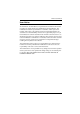
Chapter 5. The Firmware Upgrade Utility Performing the Upgrade Starting the Upgrade To upgrade your firmware: 1. Run the downloaded Firmware Upgrade Package file - either by double clicking the file icon, or by opening a command line and keying in the full path to it. The Firmware Upgrade Utility Welcome screen appears: 2. Read and Agree to the License Agreement (enable the I Agree radio button).
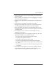
KH0116 User Manual 3. Click Next to continue. The Firmware Upgrade Utility main screen appears: The Utility inspects your installation. All the devices capable of being upgraded by the package are listed in the Device List panel. 4. If the utility detects more than one Master Device (the First Stage unit of a daisy chained installation), a dialog box appears asking you to select one of the Master devices (and all the Slave devices that are chained down from it) that you want to receive the upgrade.
Chapter 5. The Firmware Upgrade Utility 5. As you select devices, a detailed description of each appears in the Device Description panel. 6. After you have made your selection(s), Click Next to perform the upgrade. If you enabled Check Firmware Version, the Utility compares the device's firmware level with that of the upgrade files.
KH0116 User Manual Upgrade Succeeded After the upgrade has completed, a screen appears to inform you that the procedure was successful: Click Finish to close the Firmware Upgrade Utility.
Chapter 5. The Firmware Upgrade Utility Upgrade Failed If the upgrade failed to complete successfully a dialog box appears asking if you want to retry. Click Yes to retry. If you Click No, the Upgrade Failed screen appears: Click Cancel to close the Firmware Upgrade Utility. See the next section, Firmware Upgrade Recovery, for how to proceed.
KH0116 User Manual Firmware Upgrade Recovery There are basically three conditions that call for firmware upgrade recovery: When you invoke Firmware Upgrade Mode (see p. 29), but decide not to proceed with the upgrade. When the Mainboard firmware upgrade fails. When the I/O firmware upgrade fails. To perform a firmware upgrade recovery, do the following: 1. Slide the Firmware Upgrade Recovery Switch (see p. 6) to the Recover position. 2.
Appendix KH0116 Connection Table The following table indicates the relationship between the number of KH0116 units and the number of computers that they control: 1 1 - 16 9 129 - 144 17 257 - 272 25 385 - 400 2 17 - 32 10 145 - 160 18 273 - 288 26 401 - 416 3 33 - 48 11 161 - 176 19 289 - 304 27 417 - 432 4 49 - 64 12 177 - 192 20 305 - 320 28 433 - 448 5 65 - 80 13 193 - 208 21 321 - 336 29 449 - 464 6 81 - 96 14 209 - 224 22 337 - 352 30 465 - 480 7 97- 112
KH0116 User Manual Specifications Function Connectors Specification Console VGA 1 x HDB-15 F Console K/M 2 x 6 pin mini DIN F (KB - Gr; M - Pur) Computer Ports 16 x SPDB-15 F Daisy Chain Switches LEDs 1 x DB-25 F; 1 x DB-25 M Remote Con. 1 x RJ-45 FW Upgrade 1 x RJ-11 Power 3 pin AC power jack Power 1 x Rocker switch FW Recover 1 x Slide switch Reset 1 x Semi-recessed pushbutton Remote Con.
Appendix Administrator Login Failure If you are unable to perform an Administrator login (because the Username and Password information has become corrupted or you have forgotten it, for example) you can clear the login information with the following procedure: 1. Power off the KH0116 and remove its housing. 2. Short the jumper labeled J12.
KH0116 User Manual Troubleshooting Symptom Possible Cause Action Mouse and/or Keyboard not responding. Improper mouse and/or keyboard reset. Unplug the cable(s) from the console port(s), then plug it/them back in. All Station IDs display as 01. Station 1 has suddenly lost power. Wait a few seconds for the system to reinitialize the station sequence and display the proper IDs.
Index A Activate Beeper, 27 ADM, 26 Administrator functions, 26 Administrator Login Failure, 51 ALTUSEN Information, xiii Auto Scanning, 32, 36 Invoking Auto Scan, 37 Pausing Auto Scan, 37 Scan Duration, 25 Setting the Scan Interval, 36 Stopping, 37 B Beeper Activate, 27 Hotkey Control, 39 BRC, 31 Broadcast Mode, 31 C CE-250R Components, 13 Installation, 14 Operation, 15 Clear the Name List, 27 Components, 5 Computer Connection Tables, 49 D Daisy Chaining, 11 E Edit Port Names, 27 F Factory Default Set
I Installation Daisy Chaining, 11 Single Stage, 10 Invoking Hotkey Mode, 35 K KH0116 Front View, 5 Rear View, 7 L LEDs Port, 5 Station ID, 6 LIST, 23 Logout, 33 Logout Timeout, 26 LOUT, 33 O OSD Factory Default Settings, 49 Functions, 22 Hotkey, 19, 24 Logout, 33 Main Screen, 19, 20 Main Screen Headings, 21 Navigation, 21 Overview, 19 Password, 19 P Password, 19, 26 Pause, 32 Port ID Display Duration, 24 Display Mode, 25 Display Position, 24 Numbering, 17 Port LEDs, 5 Port Names, 27 Port Selection, 18
Switching Station Positions, 16 Switching station positions, 16 T Timeout, 26 Troubleshooting, 52 U Upgrading the firmware, 41 User Notice, iii Username, 26 55