
Instruction manual

17
15
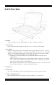
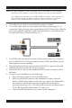
KL0116 Back View
1. Power Switch
• Turn on the KL0116 with the standard rocker power switch.
2. Power Socket
• Plug the AC power cord in the power socket.
3. Daisy Chain Port
• For Daisy Chained installations, plug the daisy chain cable into the Daisy Chain port.
The KL0116 only has a Chain Out port and is used as the master on the chain.
4. CPU Port Section
• The cables that link to the computers plug in here. Only cables specifically designed to
work with this switch can plug into the CPU port section. Do NOT use ordinary 15 pin
VGA connector cables to link computers to these ports.
NOTE: For detailed information on cables, see page 12.
5. Remote Console Port
• If you choose to use a remote console, its cable plugs into this RJ-45 connector. When a
remote and local console are present, both can access the switch.
NOTE: For detailed information on using the KL0116 with a remote console, see Chapter 6.
• The Select button located at the far right of the LCD display controls (see page 14),
toggles the KVM focus between the local (the built-in LCD display, keyboard and
touchpad) and remote (external) consoles.
6. Firmware Upgrade Port
• The Firmware Upgrade Cable plugs into the Firmware Upgrade Port’s RJ-11 connector
and transfers firmware upgrade data from the administrator’s computer to the KL0116.
7. Firmware Upgrade Recovery Switch
• This switch is in the NORMAL position during normal operation or while performing a
firmware upgrade. If the firmware upgrade operation does not successfully complete,
slide the switch to the RECOVER position; power off and restart to return the switch to
its former firmware state. When finished, slide the switch to the NORMAL position and
attempt the firmware upgrade again or use the switch with the original firmware.