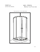
K-KA4Z - Kona INSTRUCTION MANUAL KONA CURVED GLASS SLIDING SHOWER DOOR KK005
CURVED GLASS SLIDING SHOWER DOOR Please keep this manual and product code number for future reference and replacement parts ordering if necessary.
CURVED GLASS SLIDING SHOWER DOOR READ CAREFULLY AND COMPLETELY BEFORE PROCEEDING IT IS RECOMMENDED THAT YOU WEAR SAFETY GLASSES AT ALL TIMES DURING INSTALLATION INSTALLATION OVER CERAMIC TILE If your shower door is to be installed over ceramic tile, tile should extend completely under both wall jambs. Silicone should be used to seal the line where ceramic tile meets the base. HOW TO CARE FOR YOUR DOOR Never use scouring powder pads or sharp instruments on metal work or glass panels.
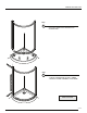
PACKAGING CHECK LIST & HARDWARE TOP TRACK WITH ROUNDED CHANNEL 11 12 1 2 10 3 4 9 5 6 7 8 BOTTOM TRACK WITH FLAT CHANNEL 1 2 3 4 WALL JAMB (2) EXPANDER (2) FIXED PANEL (2) GLASS SUPPORT /L (4) 5 6 7 8 GLASS SUPPORT /R (4) BOTTOM TRACK (1) DOOR PANEL (2) SIDE GASKET (4) 9 10 11 12 SET OF HANDLES (2) SIDE GASKET WALL JAMB SIDE (2) TOP TRACK (1) MAGNET GASKET (2) PAGE 1
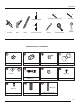
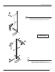
OOLS LIST 1/4” 1/8” DRILL BIT CERAMIC TILE DRILL BIT SCREWDRIVERS 5/16 SILICON DRILL LEVEL HEX NUT DRIVER PENCIL MEASURE TAPE MALLET PACKAGING CHECK LIST & HARDWARE 5 4 GLASS SUPPORT /L (4) 10 OR 9 8 GLASS SUPPORT /R (4) 12 SIDE GASKET 4) 13 14 (M4 X 8) (FOR ‘’PARIS POINT ’’ GLASS ONLY) SIDE GASKET WALL JAMB SIDE (2) MAGNETIC DOOR GASKET (2) 16 15 SCREW CAP (8) SCREW 3/8” LG (8) 17 (M4 X 35) (M4 X 8) SCREW ½” LG (4) SET OF HANDLES (2) WALL PLUG (8) SCREW 1 3/8” LG (14)
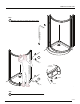
DOOR INSTALLATION STEPS Step 3 -POSITION AND CENTER THE FRAME TOGETHER WITH WALLJAMBS ONTO THRESHOLD OF SHOWER BASE. Step 4 - ADJUST AND LEVEL THE FRAME ASSEMBLY. - TRACE OUTER EDGE OF WALL JAMBS. - REMOVE FRAME ASSEMBLY FROM BASE.
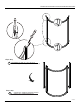
ÉTAPES D’INSTALLATION DE LA PORTE / DOOR INSTALLATION STEPS Étape / Step 1 EXTENSEUR (2)+ RAIL (2) + VIS 1 3/8’’ LG (8) EXPENDER (2) + TRACK (2) + SCREW 1 /3/8’’ LG (8) Étape / Step 2 INSÉREZ LES JAMBAGES TEMPORELLEMENT INSERT WALL JAMBS TEMPORALLY PAGE 3
DOOR INSTALLATION STEPS 5A 5 - REALIGN WALL JAMB WITH REFERENCE LINE (2). - MARK DRILLING LOCATION FOLLOWING PILOT HOLES. - DRILL HOLES BY USING SUITABLE 1/4” DRILL BIT. 5B ON BOTH SIDES 6A 6B 6C Step 6 - INSERT THE WALL PLUGS (6) AND PUT IN EACH A DROP OF SILICONE.
DOOR INSTALLATION STEPS Step 7 INSERT ONE SIDE OF FRAME INTO WALL JAMB Ins er Lower frame t e id Sl 8B Pu sh INTERIOR SHOWER SIDE e id Sl Slide 8A Pu sh Push Step 8 ENGAGE THE OTHER SIDE OF FRAME INTO WALL JAMB PAGE 6
DOOR INSTALLATION STEPS TOP TRACK INTERIOR SHOWER SIDE Step 9 FIXED PANEL (2) ON BOTH SIDE GLASS GLASS SUPPORT BOTTOM TRACK INTERIOR SHOWER SIDE A1 A A2 INTERIOR SHOWER SIDE B Step 10 GLASS SUPPORT (8) + SCREW ½” LG (8) PAGE 7
DOOR INSTALLATION STEPS Step 11 INSTALL DOOR PANELS (OPTIONAL) PUSH DOWN 13C PUSH DOWN 13A INTERIOR SHOWER SIDE 13B INTERIOR SHOWER SIDE INTERIOR SHOWER SIDE Step 12 INSERT DOOR PANELS INTO TOP & BOTTOM TRACK PAGE 8
DOOR INSTALLATION STEPS Step 13 USE HEX NUT DRIVER OR PLIERS FOR VERTICAL DOOR ADJUSTMENT 13A LOOSEN TIGHTEN 13B 13D 13C 13E VERTICAL ADJUSTMENT INTERIOR SHOWER SIDE Step 14 INSTALL SIDE PANEL GASKET ONTO DOOR PANEL 1 (1) PAGE 9
DOOR INSTALLATION STEPS Step 15 INSERT EXPANDER CAPS A B INTERIOR SHOWER SIDE Step 16 SCREW 3/8” LG (8) + SCREW CAP (8) INTERIOR SHOWER SIDE ON BOTH SIDES PAGE 10
DOOR INSTALLATION STEPS (FOR ‘’PARIS POINT ’’ GLASS ONLY) OR (FOR 6mm GLASS ONLY) Step 17 INTERIOR SHOWER SIDE INSERT SIDE GASKET WALL JAMB SIDE (2) (both sides) INTERIOR SHOWER SIDE 24 Hours Step 18 SILICONE EXTERIOR OF ( BOTTOM TRACK + ALONG WALL JAMB) PAGE 11