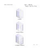
Walk-in ● Shower System L-100X-41 L-210X-33, L-210X-41 L-210TBX-33, L-210TBX-41 L006 08.
Please keep this manual and product code number for future reference and to order replacement parts if necessary.
● GENERAL INSTRUCTIONS - Read this manual carefully and completely before proceeding. - It is recommended that you wear safety glasses at all times during the installation. ● INSTALLATION OVER CERAMIC TILES - Silicone should be used to seal the gap where the ceramic tiles meet the panel. - If your shower door is to be installed over ceramic tiles, the tiles should lay completely under the wall jamb. ● NOTICE - Caulking: no sealant is required inside the shower. Unless otherwise stated.
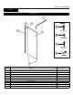
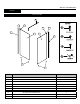
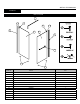
INSTALLATION MANUAL 100X-41 PARTS LISTING 4 1.2 1.3 2 1.1 3 ITEM NO. PARTS QTY 1.1 FIXED PANEL 1 1.2 EXPANDER 1 1.3 GASKET 1 2 WALL JAMB 1 3 BOTTOM GLASS CLIP 2 4 SUPPORT BAR 1 7.1 WALL PLUG #6-1 4 7.2 SELF DRILLING SCREW #8-3/8 3 7.3 SELF DRILLING SCREW #8-1 1/4 3 7.
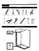
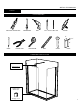
INSTALLATION MANUAL 100X-41 TOOLS REQUIRED LONG NOSE LOCKING PLIER SCREWDRIVERS DRILL Ø1/4˝& Ø1/8˝ DRILL BITS SILICONE 2˝ 1/2˝ 6˝ PENCIL CUTTING PLIER TAPE MEASURE LEVEL MALLET BLOCK COMPONENTS INSTALLATION ● Support bar See page 15-16 • Return panel • Bottom clips See page 13-14 5
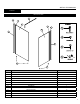
INSTALLATION MANUAL 210X-33 PARTS LISTING 4 1.2 1.3 1.2 1.3 2 1.1 1.1 2 3 3 ITEM NO. PARTS QTY 1.1 FIXED PANEL 2 1.2 EXPANDER 2 1.3 GASKET 2 2 WALL JAMB 2 3 BOTTOM GLASS CLIP 4 4 SUPPORT BAR 1 7.1 WALL PLUG #6-1 8 7.2 SELF DRILLING SCREW #8-3/8 6 7.3 SELF DRILLING SCREW #8-1 1/4 6 7.
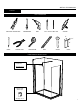
INSTALLATION MANUAL 210X-33 TOOLS REQUIRED LONG NOSE LOCKING PLIER SCREWDRIVERS DRILL Ø1/4˝& Ø1/8˝ DRILL BITS SILICONE 2˝ 1/2˝ 6˝ PENCIL CUTTING PLIER TAPE MEASURE LEVEL MALLET BLOCK COMPONENTS INSTALLATION ● Support bar See page 15-16 • Return panel • Bottom clips See page 13-14 7
INSTALLATION MANUAL 210X-41 PARTS LISTING 4 1.2 1.3 1.1 5.3 5.2 5.1 2 2 3 3 ITEM NO. PARTS QTY 1.1 FIXED PANEL 1 1.2 EXPANDER 1 1.3 GASKET 1 2 WALL JAMB 2 3 BOTTOM CLIP 4 4 SUPPORT BAR 1 5.1 RETURN PANEL 1 5.2 EXPANDER 1 5.3 GASKET 1 7.1 WALL PLUG #6-1 8 7.2 SELF DRILLING SCREW #8-3/8 6 7.3 SELF DRILLING SCREW #8-1 1/4 6 7.
INSTALLATION MANUAL 210X-41 TOOLS REQUIRED LONG NOSE LOCKING PLIER SCREWDRIVERS DRILL Ø1/4˝& Ø1/8˝ DRILL BITS SILICONE 2˝ 1/2˝ 6˝ PENCIL CUTTING PLIER TAPE MEASURE LEVEL MALLET BLOCK COMPONENTS INSTALLATION ● Support bar See page 15-16 • Return panel • Bottom clips See page 13-14 9
INSTALLATION MANUAL 210TBX-33 PARTS LISTING 4 1.3 1.2 5.3 2 1.1 5.2 5.1 2 6 3 3 ITEM NO. PARTS QTY 1.1 FIXED PANEL 1 1.2 EXPANDER 1 1.3 GASKET 1 2 WALL JAMB 2 3 BOTTOM GLASS CLIP 4 4 SUPPORT BAR 1 5.1 RETURN PANEL 1 5.2 EXPANDER 1 5.3 GASKET 1 6 TOWEL BAR 1 7.1 WALL PLUG #6-1 8 7.2 SELF DRILLING SCREW #8-3/8 6 7.3 SELF DRILLING SCREW #8-1 1/4 6 7.
INSTALLATION MANUAL 210TBX-33 TOOLS REQUIRED LONG NOSE LOCKING PLIER SCREWDRIVERS DRILL Ø1/4˝& Ø1/8˝ DRILL BITS SILICONE 2˝ 1/2˝ 6˝ PENCIL CUTTING PLIER TAPE MEASURE LEVEL MALLET BLOCK COMPONENTS INSTALLATION ● Support bar See page 15-16 • Towel bar See page 17 • Return panel • Bottom clips See page 13-14 11
INSTALLATION MANUAL 210TBX-41 PARTS LISTING 4 1.2 1.3 1.1 5.3 5.2 5.1 2 2 6 3 3 ITEM NO. PARTS QTY 1.1 FIXED PANEL 1 1.2 EXPANDER 1 1.3 GASKET 1 2 WALL JAMB 2 3 BOTTOM CLIP 4 4 SUPPORT BAR 1 5.1 RETURN PANEL 1 5.2 EXPANDER 1 5.3 GASKET 1 6 TOWEL BAR 1 7.1 WALL PLUG #6-1 8 7.2 SELF DRIILLING SCREW #8-3/8 6 7.3 SELF DRILLING SCREW #8-1 1/4 6 7.
INSTALLATION MANUAL 210TBX-41 TOOLS REQUIRED LONG NOSE LOCKING PLIER SCREWDRIVERS DRILL Ø1/4˝& Ø1/8˝ DRILL BITS SILICONE 2˝ 1/2˝ 6˝ PENCIL CUTTING PLIER TAPE MEASURE LEVEL MALLET BLOCK COMPONENTS INSTALLATION ● Support bar See page 15-16 • Towel bar See page 17 13
INSTALLATION MANUAL 100X, 210X, 210TBX 1 FIXED PANEL INSTALLATION ● THIS INSTALLATION PROCEDURE APPLIES FOR ALL RETURN PANELS INSTALLATION REGARDLESS OF QUANTITY OR ADDITIONAL FIXTURE SUCH AS TOWEL BAR. 2 1a 1a. Using a measuring tape, mark the center of the threshold of the base. 1b. Using the marking established in the previous step, run a second line up the wall. Use a level to ensure verticality of this line. 1b 1c.
INSTALLATION MANUAL 100X, 210X, 210TBX 1 CONTINUED 1e. 1e. Place the bottom clips (3) for return panel on the line traced previously following dimension shown on the plan view. Mark the screw location. Remove temporary the bottom clips to drill the base using Ø1/8” drill bit. Put silicone onto the bottom clip bottom face groove and around the hole. Finally, fasten the bottom clips to the base using the provided screws. Place the gaskets into bottom clips slots.
INSTALLATION MANUAL 100X, 210X, 210TBX 2a. SUPPORT BAR INSTALLATION Take apart the end component (A) of the support bar (4) with the provided Allen Key. 2a B 2c. Wall end component 2b Transfer the position of the bottom clip (3) to the back wall. At 82” (208cm) from the threshold mark the position (center of the cylinder ) for the support bar wall end component. MIN 82” (208cm) | MAX. 82 1/4” (209cm) 2b. A 4 Drill the back wall using a Ø1/4”drill bit. 2d.
INSTALLATION MANUAL 100X, 210X, 210TBX 2 2f. CONTINUED Loosen and rotate support bar to grab the front panel. Make sure you insert the clear gasket as shown. 2f B Clear gasket 2g. Level support bar. Tighten the set screws. 5 2g A B B.
INSTALLATION MANUAL 210TBX 3a 4 1/4” (11cm) 30” (76cm) [56312-56313] L-210TBX If the return panel hasn’t been installed yet, refer to step 1e – 1h to complete the installation. 5 3a. TOWEL BAR INSTALLATION 5 3 3b. Install the towel bar (6) as illustrated.
INSTALLATION MANUAL 100X, 210X, 210TBX 4 4a. CAULKING Silicone seal the exterior of the shower along the wall. Fill gap between glass panels and base surrounding the bottom clips (3).