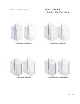
L-301X-24, L-302X-24 L-421X-32, 422X-32 L-301X-32, L-302X-32 L-421TBX-32, L-422TBX-32 L002 08.
Please keep this manual and product code number for future reference and replacement parts ordering if necessary.
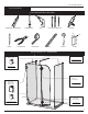
2 PEOPLES REQUIRED GENERAL INSTRUCTIONS - Read this manual carefully and completely before proceeding. - It is recommended that you wear safety glasses at all times during the installation. INSTALLATION OVER CERAMIC TILES - Silicone should be used to seal the gap where the ceramic tiles meet the fixed panel. - If your shower door is to be installed over ceramic tiles, the tiles should lay completely under the wall jamb. NOTICE - Caulking: no sealant is required inside the shower. Unless otherwise stated.
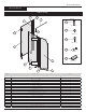
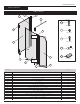
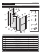
INSTALLA TION MANUAL 301X-24, 302X-24 P ARTS LISTING 2 3.2 7 3.1 HARDWARE 13.1 WALL PLUG #6-1 13.2 5 6 SCREW #8-3/8 HINGE 13.3 SCREW #8-1 1/4 3.3 a 13.4 b SCREW CAP 13.5 1 SPACING BLOCK HINGE 4 8 9 10 IT E M # P A R T S 1 Q T Y P A N E L 1 J A M B 1 3 .1 E X P A N D E R 1 3 .2 G A S K E T D O O R 2 W A L L 3 .3 R E T U R N 4 F IX E D 5 1 1 P A N E L 1 P A N E L 2 H IN G E 6 C O R N E R C L IP 2 7 S U P P O R T B A R 1 8 9 1 0 S ID E 1 3 .1 1 3 .
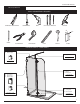
INSTALLATION MANUAL 301X-24, 302X-24 TOOLS AND MATERIALS REQUIRED LONG NOSE LOCKING PLIER SCREWDRIVERS DRILL Ø1/4" & Ø1/8" DRILLBITS SILICONE 2" 1/2" 6" PENCIL CUTTING PLIER TAPE MESURE LEVEL MALLET BLOCK INSTALLA TIONS OF COMPONENTS Return panel Bottom clips Support bar see page 13-14 see page 9-10 Hinges Door panel Front panel Corner clips Bottom clips see page 16 Side gasket Door bottom see page 1 1-12 see page 15 2
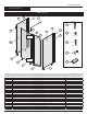
INSTALLATION MANUAL 301X-32, 302X-32 PARTS LISTING 3.1 3.2 2 7 HARDWARE 13.1 WALL PLUG #6-1 6 13.2 10 SCREW #8-3/8 HINGE 13.3 3.3 SCREW #8-1 1/4 a 13.4 b SCREW CAP 1 8 13.5 SPACING BLOCK HINGE 4 9 5 IT E M # P A R T S 1 D O O R 2 W A L L Q T Y P A N E L 1 J A M B 1 3 .1 E X P A N D E R 1 3 .2 G A S K E T 1 3 .3 R E T U R N 4 F I X E D 5 C O R N E R 7 B O T T O M B O T T O M 1 0 4 C L I P 1 G A S K E T 1 G A S K E T H A R D W A R E 1 3 1 3 .
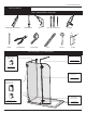
INSTALLATION MANUAL 301X-32, 302X-32 TOOLS AND MATERIALS REQUIRED LONG NOSE LOCKING PLIER SCREWDRIVERS DRILL Ø1/4" & Ø1/8" DRILLBITS SILICONE 2" 1/2" 6" PENCIL CUTTING PLIER TAPE MESURE LEVEL MALLET BLOCK INSTALLATIONS OF COMPONENTS Return panel Bottom clips Support bar see page 13-14 see page 9-10 Hinges Door panel see page 16 Front panel Corner clips Bottom clips Side gasket Door bottom see page 1 1-12 see page 15 4
INSTALLATION MANUAL 421X-32, 422X-32 PARTS LISTING 3.1 3.2 7 2 HARDWARE 13.1 11.2 5 6 11.3 10 WALL PLUG #6-1 11.1 13.2 1 2 HINGE 3.3 SCREW #8-3/8 13.3 SCREW #8-1 1/4 a 13.4 b SCREW CAP 8 HINGE 13.5 8 SPACING BLOCK 4 8 9 IT E M # P A R 1 D O O R 2 T S Q T Y 1 P A N E L J A M B 1 3 .1 E X P A N D E R 1 3 .2 G A S K E T 1 W 3 .
INSTALLATION MANUAL 421X-32, 422X-32 TOOLS AND MATERIALS REQUIRED LONG NOSE LOCKING PLIER SCREWDRIVERS DRILL Ø1/4" & Ø1/8" DRILLBITS SILICONE 2" 1/2" 6" PENCIL CUTTING PLIER TAPE MESURE LEVEL MALLET BLOCK INSTALLATIONS OF COMPONENTS Return panel Bottom clips Support bar see page 13-14 see page 9-10 Hinges Door panel Front panel Corner clips Bottom clips see page 16 Side gasket Door bottom see page 1 1-12 see page 15 6
INSTALLATION MANUAL 421TBX-32, 422TBX-32 PARTS LISTING 3.1 3.2 7 2 HARDWARE 13.1 11.1 5 6 11.3 10 WALL PLUG #6-1 11.2 13.2 1 2 HINGE 3.3 12 SCREW #8-3/8 13.3 SCREW #8-1 1/4 a 13.4 b SCREW CAP 8 HINGE 13.5 8 SP ACING BLOCK 4 9 IT E M # 8 P A R T S 1 D O O R 2 3 .2 1 P A N E L J A M B 1 E X P A N D E R 1 W A L L 3 .1 Q T Y 1 G A S K E T 3 .
INSTALLATION MANUAL 421TBX-32, 422TBX-32 TOOLS AND MATERIALS REQUIRED LONG NOSE LOCKING PLIER SCREWDRIVERS DRILL Ø1/4" & Ø1/8" DRILLBITS SILICONE 2" 1/2" 6" PENCIL CUTTING PLIER TAPE MESURE LEVEL MALLET BLOCK INSTALLATIONS OF COMPONENTS Return panel Bottom clips Support bar see page 13-14 voir page 9-10 see page 9-10 Hinges Door panel see page 16 Front panel Corner clips Bottom clips Towel bar see page 17 Side gasket Door bottom see page 1 1-12 see page 15 8
INSTALLATION MANUAL 301X, 302X, 421X, 422X, 421TBX, 422TBX 1 RETURN PANEL INSTALLATION THIS INSTALLATION PROCEDURE APPLIES FOR ALL RETURN PANELS INSTALLATION REGARDLESS OF QUANTITY OR ADDITIONAL FIXTURE SUCH AS TOWEL BAR. 1a. Using a measuring tape, mark the center of the threshold of the base. 2 1a 1b. Using the marking established in the previous step, run a second line up the wall. Use a level to ensure verticality of this line. 1b 1c.
INSTALLATION MANUAL 301X, 302X, 421X, 422X, 421TBX, 422TBX 1 CONTINUED 30 3/8" (77cm) 4 1/4" (11cm) 1e. 1e. Place the bottom clips (8) for return panel on the line traced previously following dimension shown on the plan view. Mark the screw location. Remove temporary the bottom clips to drill the base using #1/8” drill bit. Put silicone onto the bottom clip bottom face groove and around the hole. Finally, fasten the bottom clips to the base using the provided screws.
INSTALLATION MANUAL 301X, 302X, 421X, 422X, 421TBX, 422TBX 2 BOTTOM CLIPS INSTALLATION CORNER CLIPS INSTALLATION 2a. Fasten bottom clips (8) at both sides of the front panel (4) at approximately 3 ½” from the edges. 2b 3 4 FRONT PANEL 3 holes 2b. Temporarily install the corner clip (6) on the slots panels (3 & 4). Align the front panel (4) to the edge of the return panel (3) as shown.
INSTALLATION MANUAL 301X, 302X, 421X, 422X, 421TBX, 422TBX 2 CONTINUED 2d. Remove the front panel (4) by disassembling the corner clip back plate. Drill pilot hole on the base with Ø1/8” drill bit according to marking. 2d 4 2e. Remove the bottom clips from the front fixed panel (4). Apply silicone sealant into the groove on the underside of the piece and around pilot holes. Fasten the bottom clips (8) to the base with # 6 –1” provided screws and replace the gasket. 2e 8 2f.
INSTALLATION MANUAL 301X, 302X, 421X, 422X, 421TBX, 422TBX 3 SUPPORT BAR INSTALLATION 3a. Take apart the end component (A) of the. support bar with the provided Allen Key 3a 7 B WALL END COMPONENT A 3b. Transfer the position of the bottom clip (8) to the back wall. At 82” from the threshold mark the position (center of the cylinder ) for the support bar end component (A) mounting 3b MIN 82” | MAX. 82 1/4” 3c. Drill the back wall using a Ø1/4”drill bit. 3d.
INSTALLATION MANUAL 301X, 302X, 421X, 422X, 421TBX, 422TBX 3 CONTINUED 3h 3h. Insert the clear gasket as shown. Then Loosen and rotate support bar to grab the front panel. B CLEAR GASKET 3g. Level support bar. Tighten the set screws.
INSTALLATION MANUAL 301X, 302X, 421X, 422X, 421TBX, 422TBX 4 GASKETS INSTALLATION 4a 4a. Align the fixed panel side gasket to the glass panel edge. Insert it with a 2” x 6” x 1/2” block and a mallet. Trim the excess using the cutting plier. INTERIOR SHOWER SIDE 4 4b. Cut the bottom door gasket (9) as illustrated. The lip should be about 3/4” longer than the rest . 10 4 4c. Rest the door panel (1) on a fat surface. With the mallet, insert the bottom door gasket (9) at the bottom of the door.
INSTALLATION MANUAL 301X, 302X, 421X, 422X, 421TBX, 422TBX 5 HINGES INSTALLATION 5a. Fasten one side of the hinges (5) onto the fixed panel (4). Do not tighten all the way for this step to allow other door (1) adjustments. 4 5a 5a INTERIOR SHOWER SIDE 5 5b. Place the door panel vertically next to the fixed panel (4). The holes for the hinges should be aligned. 5c. Fasten the hinge on the door (1).The door panel must be leveled before tightening the hinges completely . 1 5b 5d.
INSTALLATION MANUAL 421TBX, 422TBX 6 TOWEL BAR INSTALLATION 6a. For 56305 - 56306 configurations. If installation of return panel (11) has not been performed yet please, refer to step #1 to complete the installation. 6a 11 12 6b. Install the towel bar (12) as illustrated.
INSTALLATION MANUAL 301X, 302X, 421X, 422X, 421TBX, 422TBX 7 SILICONE SEAL THE SHOWER DOOR 7a 7a. Seal the exterior of the shower along the wall with silicone. Fill gap between the glass panels and base surrounding the bottom clips (8). 7b. Inside the shower seal along the corner between the glass panels by passing trough the center of the corner clips with silicone.