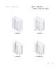
L-503X-32 L-513X-32 L-523X-32 L-523TBX-32 L003 E003
Please keep this manual and product code number for future reference and replacement parts ordering if necessary.
2 PEOPLE REQUIRED GENERAL INSTRUCTIONS - Read this manual carefully and completely before proceeding. - It is recommended that you wear safety glasses at all times during the installation. INSTALLATION OVER CERAMIC TILES - Silicone should be used to seal the gap where the ceramic tiles meet the fixed panel. - If your shower door is to be installed over ceramic tiles, the tiles should lay completely under the wall jamb. NOTICE - Caulking: no sealant is required inside the shower. Unless otherwise stated.
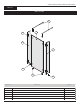
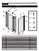
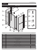
GUIDE D’INSTALLATION | INSTRUCTION MANUAL 503X-32 PARTS LISTING 3 1 4 2 2 6 5 6 IT E M # P A R T S Q T Y 1 F IX E D 2 S M A L L R E T U R N P A N E L P A N E L 1 2 3 S U P P O R T B A R 2 4 C O R N E R 4 5 6 C L IP B O T T O M C L IP L O N G B O T T O M C L IP 2 2 1
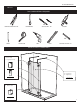
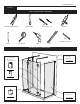
INSTRUCTION MANUAL 503X-32 TOOLS AND MATERIALS REQUIRED 1/8” 1/4” ACR YLIC DRILL BIT SCREWDRIVERS LONG NOSE LOCKING PLIER SILICONE 1/4” PENCIL TAPE MESURE DRILL LEVEL CERAMIC TILE DRILL BIT INSTALLATION OF COMPONENTS Small fixed panel Corner clips Long bottom clips Front panel Support bar see page 12 see page 10 Bottom clips see page 9 2
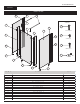
INSTRUCTION MANUAL 513X-32 PARTS LISTING 3 1 4 HARDWARE 8.3 2 11.1 8.2 2 WALL PLUG #6-1 8.1 11.2 SCREW #8-3/8 7 11.3 SCREW #8-1 1/4 a 11.4 b SCREW CAP 6 5 6 IT E M 5 # P A R T S 1 F IX E D 2 S M A L L Q T Y 1 P A N E L R E T U R N P A N E L 2 3 S U P P O R T B A R 2 4 C O R N E R C L IP 4 5 B O T T O M 6 L O N G 7 8 .2 1 1 .3 1 P A N E L 1 H A R D W A R E 1 1 1 1 .4 1 1 G A S K E T 1 1 .1 1 1 .2 J A M B R E T U R N 8 .
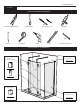
INSTRUCTION MANUAL 513X-32 TOOLS AND MATERIALS REQUIRED 1/8” 1/4” LONG NOSE LOCKING PLIER ACR YLIC DRILL SCREWDRIVERS BIT SILICONE 1/4” PENCIL TAPE MESURE DRILL LEVEL CERAMIC TILE DRILL BIT INSTALLATION OF COMPONENTS Small fixed panel Corner clips Long bottom clips Front panel Support bar see page 10 see page 12 Bottom clips Return panel panel Bottom clips see page 9 see page 14 4
INSTRUCTION MANUAL 523X-32 PARTS LISTING 8.3 3 8.1 HARD WARE 7 4 11.1 8.3 1 8.2 WALL PLUG #6-1 2 2 8.1 11.2 SCREW #8-3/8 7 8.2 11.3 SCREW #8-1 1/4 a 11.4 5 b SCREW CAP 6 5 6 IT E M 5 # P A R T S 1 F IX E D 2 S M A L L 3 S U P P O R T C O R N E R 5 B O T T O M L O N G 7 B A R 2 C L IP 4 2 J A M B R E T U R N 2 G A S K E T H A R D W A R E 1 1 .1 W A L L S E L F S E L F P L U G D R I L L IN G D R IL L IN G S C R E W 2 P A N E L 1 1 1 1 .4 2 C L IP 8 .
INSTRUCTION MANUAL 523X-32 TOOLS AND MATERIALS REQUIRED 1/8” 1/4” LONG NOSE LOCKING PLIER ACRYLIC DRILL BIT SCREWDRIVERS SILICONE 1/4” CERAMIC TILE DRILL BIT PENCIL TAPE MESURE DRILL LEVEL INSTALLATION OF COMPONENTS Small fixed panel Corner clips Long bottom clips Front panel Support bar see page 10 see page 12 Bottom clips Return panel Bottom clips see page 9 see page 14 6
INSTRUCTION MANUAL 523TBX-32 PARTS LISTING 8.3 8.1 3 HARD WARE 7 4 11.1 1 9.3 9.2 2 WALL PLUG #6-1 2 9.1 11.2 SCREW #8-3/8 8.2 10 11.3 SCREW #8-1 1/4 5 7 a 11.4 b SCREW CAP 6 5 5 6 IT E M # P A R T S 1 F I X E D 2 S M A L L R S U P P O R 4 C O R 5 7 R E T U R 8 .3 9 .1 9 .2 R 6 C L I P 2 C L I P 1 J A M B N 1 1 P A N E L 1 E X P A N D E R 1 E T U R N 1 P A N E L 1 G A S K E T 1 0 1 1 1 1 .1 1 1 .3 2 4 G A S K E T 9 .3 1 1 .
INSTRUCTION MANUAL 523TBX-32 TOOLS AND MATERIALS REQUIRED 1/8” 1/4” LONG NOSE LOCKING PLIER ACR YLIC DRILL SCREWDRIVERS BIT SILICONE 1/4” CERAMIC TILE DRILL BIT PENCIL TAPE MESURE DRILL LEVEL INSTALLATION OF COMPONENTS Small fixed panel Corner clips Long bottom clips Front panel Support bar see page 10 Bar á serviette Towel bar see page 12 see page 16 Bottom clips Return panel Bottom clips see page 9 see page 14 8
INSTRUCTION MANUAL 503X, 513X, 523X, 523TBX 1 BOT TOM CLIPS INSTALLATION 1a 1a. Using the measuring tape, mark the center of the threshold of the base. Find the center of the exposed base and draw a line to the center of the threshold. The line must be perpendicular . Place both bottom clips (5) along the line of the center of threshold. Mark the screw location following the dimensions shown in the drawing. Dimensions on the drawing are for ABN3672 base installation. 5 center of exposed base 1b.
INSTRUCTION MANUAL 503X, 513X, 523X, 523TBX 2 SUPPORT BARS INSTALLATION 2a. Take apart the end component of the support bar with the provided Allen Key. 2a 3 B WALL END COMPONENT A 2b. Transfer the position of the bottom clip (5) to the back wall. At 82” from the threshold mark the position (center of the cylinder A) for the support bar end component mounting. 2b 2d. Apply a bead of silicone in each hole and insert the wall plugs. Proceed to fasten the wall end components onto the wall.
INSTRUCTION MANUAL 503X, 513X, 523X, 523TBX 2 CONTINUED 2f 2f. Place the front fixed panel into the bottom clips (5) attached to the base. Insert the clear gasket as shown. Then Loosen and rotate support bar to grab the front panel. B B CLEAR GASKET 5 CLEAR GASKET 2g. Level support bar. Tighten the set screws.
INSTRUCTION MANUAL 503X, 513X, 523X, 523TBX 3 LONG BOTTOM CLIPS INSTALLATION CORNER CLIPS INSTALLATION 3a 3a. Temporarily install the corner clips(4) onto the glass panels (1 & 2). Align the edge of the small return panels onto the back face of the front panel as shown in the detail. Holding the glasses from the front install corner clip front plate onto front panel slots. Slide the corner clip until it meets the side fixed panel holes.
INSTRUCTION MANUAL 503X, 513X, 523X, 523TBX 3 3c. CONTINUED 3c Remove the small fixed panel by unscrewing the corner clip back plate. On the marked position drill the base with a drill bit 1/8”. Put silicone onto the bottom clip bottom face groove and around the hole. Fasten it to the base with screw #6-1”. Install the provided gasket. 6 3d. Placed inside the shower silicone seal along the corner between the glass panels all the way long trough out the corner clips.
INSTRUCTION MANUAL 503X, 513X, 523X, 523TBX 4 RETURN PANEL INSTALLATION THIS INSTALLATION PROCEDURE APPLIES FOR ALL RETURN PANEL INSTALLATIONS REGARDLESS QUANTITY OR ADITTIONAL FIXTURE AS TOWEL BAR. 4a 4a. Using a measuring tape, mark the center of the threshold of the base 4b. Using the marking established in the previous step, run a second line up the wall. Use a level to ensure verticality of this line. 4c.
INSTRUCTION MANUAL 503X, 513X, 523X, 523TBX CONTINUED 4e 5 30 3/8" 4e. Place the bottom clips (5) for return panel on the line traced previously following dimension shown on the plan view. Mark the screw location. Remove temporary the bottom clips to drill the base using #1/8” drill bit. Put silicone onto the bottom clip bottom face groove and around the hole. Finally, fasten the bottom clips to the base using the provided screws. Place the gaskets into bottom clips slots. 4 1/4" 4 5 5 5 4f.
INSTRUCTION MANUAL 523TBX 5 TOWEL BAR INSTALLATION 5a. Install the towel bar (10) as illustrated. 5a 9.2 5b. Silicone seal the exterior of the shower along the wall. Fill gap between glass panels and base surrounding the bottom clips (8).