L-CSSY 08/10 Walk-in ● Shower System L012
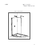
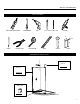
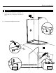
ABSL66-18L ABSL66-18R Left side base Right side base 2 PEOPLE REQUIRED
Please keep this manual and product code number for future reference and replacement parts ordering if necessary. GENERAL INSTRUCTIONS • Read this manual carefully and completely before proceeding. • It is recommended that you wear safety glasses at all times during the installation. INSTALLATION OVER CERAMIC TILES • Silicone should be used to seal the gap where the ceramic tiles meet the panel.
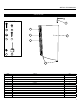
INSTALLATION MANUAL PARTS LISTING 1 6 9 2 4 7 10 8 11 3 5 11 ITEM PARTS QTY 1 SUPPORT BAR 1 2 WALL JAMB 1 3 PANEL 1 4 EXPANDER 1 5 GASKET 1 ITEM HARDWARE QTY 6 WALL PLUG 4 7 SCREW CAP 4 8 BACK SCREW CAP 4 9 PAN SELF DRILLING SCREW# 8- 3/8” 3 10 PAN SELF-DRILLING SCREW # 8- 1-1/4” 3 11 BOTTOM GLASS CLIP 2 4
INSTALLATION MANUAL TOOLS REQUIRED LONG NOSE LOCKING PLIER SCREWDRIVERS DRILL Ø1/4˝& Ø1/8˝ DRILL BITS SILICONE 2˝ 1/2˝ 6˝ PENCIL CUTTING PLIER TAPE MEASURE LEVEL MALLET BLOCK COMPONENTS INSTALLATION • Lani bar • Wall jamb See page 8-9 See page 6 • Return panel • Bottom clips See page 7 5
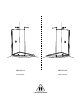
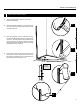
INSTALLATION MANUAL 1 FIXED PANEL INSTALLATION 1a. Using a measuring tape, mark the center of the threshold of the base. 1b. Using the marking established in the previous step, run a second line up the wall. Use a level to ensure verticality of this line. 1c. Place the wall jamb onto the wall while ensuring that the wall jamb slotted holes are centered to the center line. The side holes of the wall jamb should face the interior of the shower.
INSTALLATION MANUAL 1 CONTINUED 1e. 1e. traced previously. Mark the screw location. The clips should be placed 1” from the edge of the glass. Remove temporary the bottom clips to drill the base using Ø1/8” drill bit. Put silicone onto the bottom clip bottom face groove and around the hole. Finally, fasten the bottom clips to the base using the provided screws.Place the gaskets into bottom clips slots. 1f.
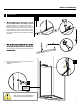
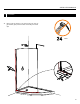
INSTALLATION MANUAL 2 2a. 2b. SUPPORT BAR INSTALLATION Take apart the end component (A) of the support bar with the provided Allen Key. Place the bar on the glass temporary and level the bar. Mark the location of the bar on the wall then remove the support bar. 2c. Drill the back wall using a Ø1/4”drill bit. 2d. Apply a bead of silicone in the hole and insert the wall plug. Proceed to fasten the wall end components (A) onto the wall. 2e.
INSTALLATION MANUAL 2 2f. 2g. CONTINUED Loosen and rotate support bar to grab the front panel. Make sure you insert the clear gasket as shown. 2f Level support bar. Tighten the set screws. B Clear gasket A 2g B B.
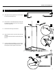
INSTALLATION MANUAL V4302Q V4303Q V56302Q V56303Q V4302M V4303M V56302M V56303M 3 3a. CAULKING Silicone seal the exterior of the shower along the wall. Fill gap between glass panels and base surrounding the bottom clips.
INSTALLATION MANUAL Notes