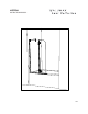
L-RTSZ24 INSTRUCTION MANUAL L010
Please keep this manual and product code number for future reference and to order replacement parts if necessary.
INSTRUCTION MANUAL ● Table of Contents MODEL NUMBER............................................... 2 GENERAL INSTRUCTIONS .................................... 3 INSTALLATION OVER CERAMIC TILES ....................... 3 NOTICE ......................................................... 3 CARE FOR YOUR FRAMELESS SHOWER DOOR ............. 3 PARTS LISTING................................................. 4 PROVIDED HARDWARE........................................ 5 TOOLS AND MATERIALS REQUIRED ...................
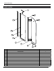
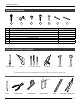
INSTRUCTION MANUAL PARTS LISTING 1 9 HINGE 2 8 3b 3c 3a HINGE 4 5 7 6 ITEM PARTS QTY 1 SUPPORT BAR 1 2 WALL JAMB 1 3a SIDE PANEL 1 3b EXPANDER 1 3c GASKET 1 4 ALUMINUM “U” CHANNEL 1 5 HINGE 2 6 LEVELING BLOCKS 2 7 BOTTOM DOOR GASKET 1 8 DOOR PANEL 1 9 SIDE PANEL GASKET 1 4
INSTRUCTION MANUAL PROVIDED HARDWARE 10 11 ITEM 12 13 14 15 16 HARDWARE QTY 10 WALL PLUG 4 11 SCREW CAP 4 12 SELF DRILLING SCREW 3 13 SELF-DRILLING SCREW 3 14 FLAT HEAD SCREW 1 15 CLEAR SETTING BLOCK 2 16 CLEAR SETTING BLOCK 2 TOOLS AND MATERIALS REQUIRED * SCREWDRIVERS DRILL 1/4˝& 1/8˝ DRILL BITS SILICONE HAMMER MALLET * If the shower panels are to be assembled on ceramic tiles, use a 1/4˝ drill bit for ceramic tiles.
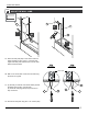
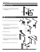
INSTRUCTION MANUAL 1 MOUNT THE WALL JAMB. 10 2 2 1C 1A 1B 13 1D 1A. Place the wall jamb (#2) on the center of the tub ledge and align it using a level. Trace the outer edge of the wall jamb and the holes onto the wall. Remove the wall jamb. TOP VIEW TOP VIEW WALL STUD 1B. With a 1/4˝ drill bit, drill 3 holes into the wall using the marks as a guide. 1C. (a) Should you find the wood studs directly behind the drilled hole location, skip this step.
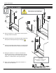
INSTRUCTION MANUAL 2 FASTEN THE “U” CHANNEL. 3 2 COVER THE PLIER’S TEETH BEFOREHAND TO AVOID SCRATCHING THE ALUMINUM PARTS. 2B 2B 2 4 2C 3 2A 2A. Place the aluminum “u” channel (#4) on the fixed panel and align it with the wall jamb. 4 2B. Slide the fixed panel over the wall jamb (#2). Secure the fixed panel to the wall jamb using a locking plier. 2 2D 2C. Trace the outer edges of the aluminum “u” channel (front and side) on the tub threshold. Remove the fixed panel. 2D.
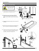
INSTRUCTION MANUAL 3 INSTALL THE FIXED PANEL. IF THE PANELS NEED MORE ADJUSTMENTS, SHIM WITH 1/8” CLEAR SETTING BLOCKS (ITEM#15), PRIOR TO FIXED PANEL. 3A 3B 3 2 3b 3A. Reposition the fixed panel on the wall jamb and in the aluminum “u” channel. Secure it with the plier. 3B. Combine the 3 3/8˝ screws (#12) with the inner screw caps (#11b). Fasten the fixed panel. 3C. Snap the screw caps (#11a) over the screws. 4 3a 12 11b 11a INTERIOR SHOWER SIDE 3C INSERT THE FIXED PANEL GASKET.
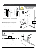
INSTRUCTION MANUAL 5 INSTALL THE HINGES. 5 5A. Fasten one side of the hinges (#5) to the fixed panel. Do not tighten all the way for this step to allow other door adjustments. 3 INTERIOR SHOWER SIDE 6 FASTEN THE SUPPORT BAR. 1b 6A. Loosen the set screws located in the connector (#1c). 6B. Pivot the connector to orient the glass clip (#1d) towards the fixed panel. 1a 6A 6B 1d 6C 1c Unscrew the glass clip. Align the slotted hole to the fixed panel.
INSTRUCTION MANUAL 7 INSTALL THE DOOR PANEL. 7 8 IT IS BEST TO HAVE 2 PEOPLE WORKING ON THIS STEP. LIP 7A. Cut the bottom door gasket (#7) as illustrated. The lip should be about 3/4˝ longer than the rest. 7A 8 3 7B. Rest the door panel on a flat surface. With the mallet, insert the bottom door gasket (#7) at the bottom of the door. Make sure the lip faces the bath side. 7 4 7C. Install the 2 leveling blocks (#6) onto the bottom lip of the gasket. FINAL RESULT 8 7 7D.
INSTRUCTION MANUAL 8 SILICONE SEAL THE EXTERIOR. HOURS 8A. Silicone seal the exterior of the shower along the wall and the aluminum “u” channel (#4).
PRODUCTION SPECS 1 9 8 2 3b 3c 3a 4 5 7 6 ITEM PARTS QTY 1 SUPPORT BAR 1 2 WALL JAMB 1 3a SIDE PANEL 1 3b EXPANDER 1 3c GASKET 1 4 ALUMINUM “U” CHANNEL 1 5 HINGE 2 6 LEVELING BLOCKS 2 7 BOTTOM DOOR GASKET 1 8 DOOR PANEL 1 9 SIDE PANEL GASKET 1 10 ITEM 11 12 13 14 15 16 HARDWARE QTY 10 WALL PLUG 4 11 SCREW CAP #8/8 4 12 SELF DRILLING SCREW #8-3/8 3 13 SELF-DRILLING SCREW #8-1 1/4 3 14 FLAT HEAD SCREW #6-3/4 1 15 CLEAR SETTING BLOCK 2 16 CL